User’s Guide
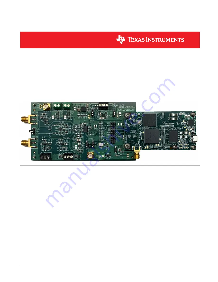
ADS127L11EVM-PDK Evaluation Module
Art Kay
ABSTRACT
This user's guide describes the characteristics, operation, and use of the
ADS127L11
evaluation module (EVM).
This kit is an evaluation platform for the ADS127L11, which is a 24-bit, high-speed, wide-bandwidth, delta-sigma
(ΔΣ) analog-to-digital converter (ADC). The ADS127L11 offers excellent ac and dc performance, along with
multiple internal digital filter options, making the device useful for a wide variety of data acquisition applications.
The ADS127L11EVM eases the evaluation of the device with hardware, software, and computer connectivity
through the universal serial bus (USB) interface. This user's guide includes complete circuit descriptions,
schematic diagrams, and a bill of materials. Throughout this document, the abbreviation
EVM
and the term
evaluation module
are synonymous with the
ADS127L11EVM
.
Table of Contents
1 EVM Overview
.........................................................................................................................................................................
3
1.1 ADS127L11EVM Kit...........................................................................................................................................................
3
1.2 ADS127L11EVM Board......................................................................................................................................................
4
1.3 ADS127L11EVM-PDK-GUI Unsupported Features...........................................................................................................
4
2 EVM Analog Interface
.............................................................................................................................................................
5
2.1 EVM Analog Input Options.................................................................................................................................................
5
2.2 ADC Connections and Decoupling.....................................................................................................................................
5
2.3 ADC Input Drive Amplifiers................................................................................................................................................
6
2.4 VCOM Buffer......................................................................................................................................................................
7
2.5 Onboard Voltage Reference...............................................................................................................................................
7
2.6 External Voltage Reference...............................................................................................................................................
8
2.7 Clock Tree..........................................................................................................................................................................
9
3 Digital Interface
.....................................................................................................................................................................
10
3.1 Serial Interface (SPI)........................................................................................................................................................
10
3.2 I2C Bus for Onboard EEPROM........................................................................................................................................
10
4 Power Supplies
.....................................................................................................................................................................
11
4.1 Power Connection and Configuration...............................................................................................................................
11
4.2 Low Dropout Regulator (LDO).........................................................................................................................................
12
5 ADS127L11EVM Software Installation
................................................................................................................................
13
6 EVM Operation
......................................................................................................................................................................
15
6.1 Connecting the Hardware................................................................................................................................................
15
www.ti.com
Table of Contents
SBAU351 – APRIL 2021
Submit Document Feedback
ADS127L11EVM-PDK Evaluation Module
1
Copyright © 2021 Texas Instruments Incorporated


