


4 IDAC / Sensor Bias
ADS126xEVM Software
3.4.4
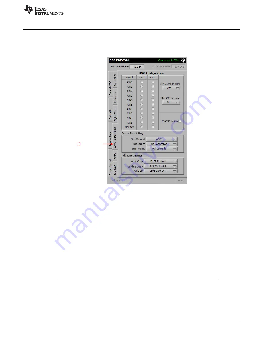
Tab 4: IDAC / Sensor Bias
shows the
IDAC \ Sensor Bias
tab controls. The
IDAC Configuration
controls configure the IDAC
direction, magnitude, and rotation. The IDACs require the internal reference to be enabled on tab 2
(
Reference
).
Figure 20. Tab 4 Settings
The
Sensor Bias Settings
controls are used to enable burnout current sources or bias resistor connections
prior to ADC1 (or ADC2) for detecting sensor open circuits or biasing floating sensors. Only use burnout
current sources to verify the sensor connection. For best results, disable the burnout current source after
the sensor connection is verified and before measuring the sensor output. Make sure to account for the
analog filter settling time when enabling or disabling the burnout current source.
The
Additional Settings
controls configure other sensor bias-related functions:
Input Chop—
enables or disables the global input chop feature of the ADS126x.
When enabled, input chopping reduces offset and offset drift errors.
Settling Delay—
configures the initial conversion delay before ADC1 begins converting.
The default settling delay provides time for PGA1 to settle when a step input occurs.
AINCOM Bias—
enables or disables the mid-supply level-shift function on the AINCOM pin
Input Chop
and
AINCOM
are duplicated on tab 1 (
Input MUX
) for quick access.
NOTE:
The software does not allow for simultaneous GPIO, Test DAC, IDAC, or VBIAS functions to
be enabled on the same pin.
23
SBAU206 – April 2015
ADS126xEVM-PDK
Copyright © 2015, Texas Instruments Incorporated