Analog Input
Low-Noise
Signal Generator
USB 3.0 Cable
+5-VDC Power Supply Cable
PC Running
HSDC Pro
Power
Switch
ADC32RF45 EVM
TSW14J56EVM
Low-Noise
Power Supply
+5 VDC at 3 A
2949.12 MHz, +15 dBm
Mini-USB Cable
CLK
Analog Input
Low-Noise
Signal Generator
1900 MHz, +15 dBm
2949.12-MHz
Bandpass Filter
1900-MHz
Bandpass Filter
AINP
Low-Noise
Power Supply
+5 VDC at 3 A
ADC32RFxx Quick-Start Procedure ADC32RF45 Bypass LMFS82820 Mode
7
SLAU620A – April 2016 – Revised May 2016
Copyright © 2016, Texas Instruments Incorporated
ADC32RF45/RF80 EVM Quick Startup Guide
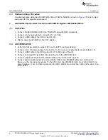
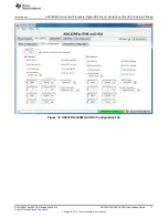
Figure 2. ADC32RFxxEVM GUI Bench Setup Block Diagram
Fs = 2.94912 GHz, 5-Sample Example
This example captures data from channel A of the ADC32RF45 EVM sampling at 2.94912 GHz with a
1900-MHz input source. This procedure uses a .cfg file to set up the LMK04828 clock device first, and
then another .cfg file to set up the ADC. This is always the required sequence. The ADC requires the
device clock and SYSREF signals to be present
before
the ADC can be properly configured.
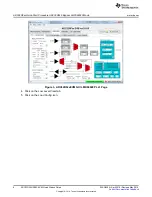
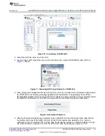
1. Open the ADC32RFxx EVM GUI.
2. Verify that the green
USB Status
indicator is lit. If it is not lit, click the
Reconnect?
button and check the
USB Status
indicator again. If it is still not lit then verify the EVM is connected to the computer through
USB. Whenever the USB link is disturbed, the GUI must obtain a new handle to address the proper
USB port, and the
Reconnect?
Button does that.
3. On the PLL1 tab of the LMK04828 tab, press the
RESET
button.


