Quick Start Guide
6
SLAU620A – April 2016 – Revised May 2016
Copyright © 2016, Texas Instruments Incorporated
ADC32RF45/RF80 EVM Quick Startup Guide
2.3
Hardware Setup Procedure
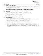
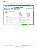
A typical test setup using the ADC32RF45 EVM and TSW14J56EVM is shown in
. This is the test
setup used for the quick-start procedure.
3
ADC32RFxx Quick-Start Procedure ADC32RF45 Bypass LMFS82820 Mode
3.1
TSW14J56
1. Connect the ADC32RF4x EVM to the TSW14J56 using the FMC connectors.
2. Connect a 5-V power supply to connector J11 (+5V IN).
3. Connect a USB cable to the USB connector (J9).
4. Flip the power switch (SW6) to the “ON” position
3.2
ADC32RF4x EVM
1. Verify the clocking selection jumper JP3 is set to EXT for external clocking.
2. Connect a 5-V, 3-A power supply to connector J15. Do not use a supply that is rated less than 3 A.
3. Connect a USB cable to the USB connector (J11 bottom side of board).
4. Connect an analog RF signal from the signal source to the AINP SMA (J2).
5. Connect a signal generator set for 2.94912 GHz to the external clock input J5.
6. Connect another signal generator set for 2.94912 GHz to the LMK04828 reference clock input J7.
(Make sure the two signal generators for the ADC clock and LMK04828 clock are synchronized to the
same timebase, or use a single signal generator and a splitter to generate two copies of the clock to go
to the EVM.)


