www.ti.com
List of Figures
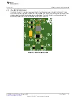
1
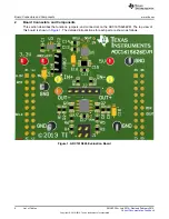
ADC161S626 Evaluation Board
...........................................................................................
6
2
5 V and 3.3 V Power Supply
...............................................................................................
7
3
Reference Voltage VREF
...................................................................................................
7
4
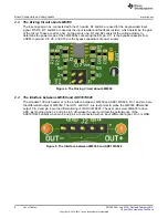
The Driving Circuit about LM8350
.........................................................................................
8
5
The Interface between LM8350 and ADC161S626
.....................................................................
8
6
The ADC161S626 Circuit
...................................................................................................
9
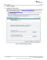
7
ADC1x1S62x Installation Directory
......................................................................................
10
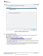
8
ADC1x1S62x Installation Finish
..........................................................................................
11
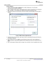
9
USB Firmware Upgrade Window
.........................................................................................
12
10
Driver Not Installed
.........................................................................................................
13
11
Driver Authentication Warning
............................................................................................
14
12
Example COM Port Number
..............................................................................................
14
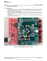
13
ADC161S626EVM Hardware Connection
..............................................................................
15
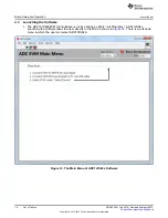
14
The Main Menu of ADC1x1S62x Software
.............................................................................
16
15
Selectable Fields in GUI
...................................................................................................
17
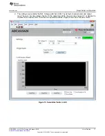
16
Testing in the GUI
..........................................................................................................
18
17
Top Assembly Layer
.......................................................................................................
19
18
Top Layer Routing
.........................................................................................................
20
19
Power Layer Routing
......................................................................................................
21
20
Ground Layer Routing
.....................................................................................................
22
21
Bottom Layer Routing
......................................................................................................
23
22
ADC161S626EVM DUT Schematic
......................................................................................
24
3
SNOU130A – July 2014 – Revised February 2015
List of Figures
Submit Documentation Feedback
Copyright © 2014–2015, Texas Instruments Incorporated


