Operation manual Pneumator
∙
Testo Industrial Services
∙
Version 1.4
∙
2019
∙
Page 14
o
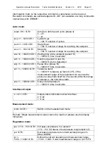
Upper middle and right: Indication of the maximum pressure and unit
o
Middle left: Number of past and future cycles
o
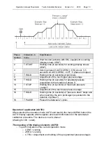
Middle: Phase number (compare chart above), phase-duration, reference
pressure value
o
Bottom to the left: Battery load indicator (at mains operation: plug symbol)
o
Bottom in the middle: percental indication of the current set pressure stage (in
percent of the maximum pressure)
o
Bottom right: Absolute value of the current set pressure stage.
Example
(see illustration):
- Maximum pressure = 10 mbar
- Currently phase 1 (waiting for OK), venting
- Currently pressure = 0,002 mbar,
- first of ten cycles
- power supply operation (lower left)
Retrieval of calibration data:
The programmed calibration cycles will be started by the OK button. As soon as the
display (middle) indicates a stable value in the phases 10 or 16, the adequate
calibration data can be registered (please note: the values will not be stored):
- Physical unit: Value in the upper right of the display
- Set value: value in the lower right of the display
- Actual value of the test device: Display of the test device
- Reference value: Middle of display
Leakage test (LEAK)
The leakage test is not available in the AUTO-Modus.
Leaving the operating mode AUTO
Pressing the MENU button, the AUTO-Modus will be canceled and left at any time.
While the menu is shown, the equipment is venting (VENT) in order to reduce the
internal pressure of the pump. If desired, you can switch to another mode (CTRL,
MESS).

