


FF-MM-370-REV - 01
Page 8
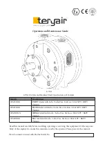
Operation and Maintenance Guide 6 VM Air Motor Series
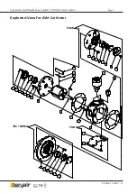
Dis assembly and Re-assembly
Disconnect air supply and vent all air lines.
Air stream from product may contain solid or
liquid material that can result in eye or skin
damage.
Flush this product in a well ventilated area.
Do Not use kerosene or other combustiblesol-
vents to flush this product.
Failure to follow these instructions can result
in eye injury or other serious injury.
Always open from the back side first.
Use proper tools to open the fasteners.
a. Unscrew Allen Bolts(11) with Spring
Washer (19) from Bearing Cap (5) from
Rear Flange (3). Remove O-ring (9) from
Bearing Cap (5) and replace with new one
(if found damaged).
b. Unscrew Allen Bolts (14) with Spring
Washer (18) from Rear Flange (3) & re-
place Shim (17) with new one (if found
damaged).
c. Now remove Ball bearing (7) from Rear
Flange (3) using mallet and replace it with
new one (if worn-out).
d. Now remove the Rotor Shaft (4) with Rotor
Blades (15) from the Motor Housing (1),
Now remove the Rotor Blades (15), Leaf
Spring (20) & Pin (17) from Rotor Shaft (4)
and replace them with new ones (if found
damaged).
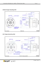
e. To remove the Front Bearing Cap (6) from
Front Flange (2), unscrew CSK Bolt (21)
from it. The O-ring (9) and Oil Seal (10)
can be now removed from Front Bearing
Cap (6). Replace with new ones (if found
damaged).
f. Now remove Ball bearing [ (7) for Face/
Foot mount models and (8) for IEC /Nema
mount models) from Front Flange (2) by
using puller. Replace it with new ones (if
worn-out).
g. After installing bearing & seal then install
the Front Bearing Cap (6) on Front Flange
(2) by fastening CSK Bolts (21).
h. Now insert Pins (16) into the Rotor
Shaft’s (4) through holes (use small
amount of grease to prevent Pins to fall
during assembly). Now insert the Rotor
Shaft (4) into the Motor Housing (1) and
Front Flange bearing using press/mallet
precisely and ensure that rotor face is not
above the housing face.
i. Now place the Leaf Spring (20) on Rotor
Blades (15), ensure that leaf spring one
end is inside the slot of Rotor Blade (15).
j. Insert the above blade assembly one at a
time into Rotor Shaft (4).
k. Now follow the above steps ‘c’ & ‘b’ in
reverse manner to assemble the motor.
l. Now after assembly, ensure that Rotor
Shaft (4) is rotating smoothly inside, else
tap lightly on the rotor shaft front end or
rear end until you obtain smooth rotation
of Rotor Shaft (4).
m. Once smooth rotation is achieved follow
the step ‘a’ in reverse manner and com-
plete the assembly.


