10521 Gulfdale, San Antonio, TX 78216 I
www.terrawave.com
I Email:
I Phone: 210-375-8482
Version 1.1 - Page 8
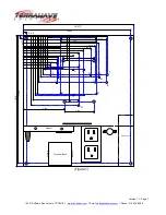
Hole Size Chart
Hole
Size
&
Thread
A
=
7/32” through hole – not threaded
B, C, D, I, J =
8-32 threaded hole
E, F, G
=
10-32 threaded hole
H
=
6-32 threaded hole
Hole usage ledger
Hole
Used
for
A
Mounting holes to mate up with 10-32 thread x 2” standoffs
B
Cisco
350
Metal
Case
C & F
Cisco 340 & 350 Plastic Case (F is for 10-32 locking post)
D
Cisco 1200 and 3Com 8250
I & E
Proxim AP (I is for 10-32 locking post)
J
Cisco
1130
AP
H & G
Symbol 4131 (G is for 10-32 locking post)
Customer Provided WLAN/Networking Mounting Screws
Qty
Description
4
10-32 x 3/8” counter sunk – Philips head
4
8-32 x 3/8” round Philips head
2
6-32 x 3/8” round Philips head
1
10-32 locking post (TerraWave has sample)
3
8-32 x 3/8” flat head Philips head
Enclosure Mounting Holes
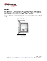
Mounting holes have been provided in the back of the enclosure. These holes provide easy
and convenient mounting of the unit.
Hole Plugs
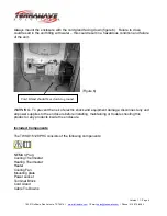
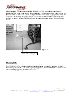
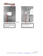
The enclosure is supplied with pre-installed hole plugs which have been inserted into the
mounting holes. These plugs will need to be removed before mounting the unit. The plugs
are easily removed by squeezing the lock clips on the inside of the unit. Once the lock clips
of been pushed in, the hole plugs will easily slide out of the enclosure. Refer to figure 2.


