


Page 41
Commissioning information
Before commissioning the TERRA heat pump, the hea-
ting side must be checked for tightness, rinsed thorough-
ly, filled and bled carefully.
Commissioning requirements :
The heating and any storage tank must be filled and
•
bled.
The electrical installation must be complete and fuse-
•
protected in line with legal requirements.
The heat pump may only be switched on if it is filled on
•
the cold side and on the heating side, and if the electri-
cal connections have been checked.
During commissioning, the flow temperatures must also
•
be set. The switch-off point of 55°C should be checked
and the set shut-down temperature changed as neces-
sary.
The heat pump is equipped with a start-up delay of
•
10 minutes so that the compressor only starts running
after this period.
If the heat pump is to be drained on the heating side for
•
frost protection, the connection hose on the heat pump
return (plate heat exchanger) must be unfastened.
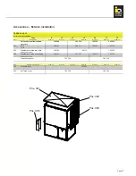
The clamps on the top part (for fastening
the panels) must be tightened securely
using an Allen key before the machine is
switched on.
Installing RFF room sensor
With a room sensor the room temperature can be monito-
red, the required room temperature can be adjusted and
the operating mode for a heating circuit can be changed
remotely.
The bus address on the offset roomstat is used to set
which heating circuit the room sensor and the operating
mode adjustment are set for.
The connection is made via a 4-pole data bus.
Recommended shielded connecting cable: J-Y (ST) Y 2
x 2 x 0.6. It is essential here that the assignments to the
connecting terminals (data bus line A and B as well as
power 12 V and GND) are correct.
Setting the bus address (heating circuit number)
The RFF address is set via a rotary coding switch inside
the room sensor according to the table below:
Device
num-
ber
Heating circuit
function
heating
circuit
number
Basic controller
1st central unit
1
mixer circuit 1
mixer circuit 2
Boiler circuit
1
2
3
Heating circuit
extension
2nd central unit
2
mixer circuit 1
mixer circuit 2
Boiler circuit
4
5
6
Heating circuit
extension
3rd central unit
3
mixer circuit 1
mixer circuit 2
Boiler circuit
7
8
9
Heating circuit
extension
4th central unit
4
mixer circuit 1
mixer circuit 2
Boiler circuit
A
B
C
Heating circuit
extension
5th central unit
5
mixer circuit 1
mixer circuit 2
Boiler circuit
D
E
F


