background image


Care and Maintenance


7


TC29  


67

7.9.5 Air filter, air intake  


All maintenance work on the air intake 
system must be carried out with the 
engine off. 

Do not start the engine while the filter 
cartridge is removed. 


7.9.5.1 Dust ejection valve 

 The dust ejection valve (53/1) is largely 

maintenance-free. 

 Any baked-on dust can be removed by 

squeezing the valve together. 


7.9.5.2 Air intake 

  Clean impurities (leaves, etc.) from the air 

intake section before the air filter. 

  Check the air filter attachment for damage and 

repair or replace, if necessary. 

  Check the tightness of the air duct after the air 

filter.  

  Examine rubber parts for damage. 


Replace damaged parts immediately. 


7.9.5.3 Cartridge maintenance interval  

Air filter - main cartridge 

  The air filter main cartridge must be replaced 

when, during operation, the filter clogging 
indicator lamp (54/21) in the instrument panel 
lights up, actuated by the service switch. 

  A brief delay in maintenance does not result in 

lower filter efficiency. 

Air filter - safety cartridge  

The air filter - safety cartridge must be replaced in 
the following cases: 

 after the third maintenance of the main 

cartridge 

  when it has reached the maximum service life 

of two years  

 if the service indicator switches on after 

maintenance of the main cartridge has just 
been performed 

  if the main cartridge is damaged  

  if the safety cartridge is damaged 


1

HR12-03-53


Fig. 53-Air filter 


TC35-03-54

21


Fig. 54-Operation 

Summary of Contents for TC29

Page 1: ...OPERATING INSTRUCTIONS Language version EN Edition 2012 02 Order number 5780210593 From vehicle ID No TC00290815 Original operating instructions tc29 Crawler Excavator tc29 Crawler Excavator...

Page 2: ...0 7951 9357 671 E Mail info terex compact com www terexconstruction com Please complete before commissioning the crawler excavator Vehicle model Vehicle ID No Year of construction Commissioned on Dea...

Page 3: ...very loading transportation 13 2 19 Monitoring and inspections 14 2 20 Fire protection 14 2 21 Emergency exit 14 2 22 Other dangers 14 3 Technical data 15 3 1 Views 15 3 2 Engine 18 3 3 Electrical sys...

Page 4: ...ection parts and aids 53 7 6 Care and cleaning 54 7 7 Notes for winter operation 54 7 8 Checking maintenance and inspection plans 55 7 8 1 Initial inspection delivery handing over inspection 55 7 8 2...

Page 5: ...vator installation is not working 82 8 6 Decrease in machine s performance 82 8 7 Machine is working too slowly and hydraulic oil is becoming too hot 82 8 8 Uppercarriage is slewing too far 82 8 9 Wor...

Page 6: ...Table of Contents TC29...

Page 7: ...included in these operating instructions We reserve the right to make improvements on the machine within the scope of impending technical developments without incurring any obligation to change these...

Page 8: ...life Insist that only original Terex spare parts are used in the event of any repair work In this way you will have a product of lasting high quality thereby ensuring that your machine maintains its...

Page 9: ...collected and disposed of If the substances listed above do reach the soil the leak or outlet must be stopped immediately and the fluid must be cleaned up with a suitable absorbent material If necess...

Page 10: ...washing system Travel speed fast Travel speed slow Horn Working floodlight s Rotating beacon Dozer blade Hydraulic rock breaker Working hydraulics cut off Fire extinguisher Danger of injury Observe n...

Page 11: ...d power level 92 9 dB A 5 Guaranteed sound power level 94 dB A 6 Applied harmonized standards EN ISO 12100 EN 474 1 EN 474 5 7 Document editor who is authorized to compile technical documentation Maik...

Page 12: ...be observed 2 2 Proper use The earth moving machine with standard bucket equipment is intended solely for work which is suitable for the function of the machine and its work implements Such work invol...

Page 13: ...check must be carried out to ensure that the first aid box is at hand and that its contents comply with regulations Personnel must be aware of the location and method of operation of the fire extingui...

Page 14: ...etc If the above safety distance cannot be maintained the area between solid objects and the working zone of the earth moving machine must be blocked off If conditions are such that the machine operat...

Page 15: ...re kept with the machine according to the traffic regulations valid in the user s country e g in Germany StVZO and that the driver has the appropriate license as required by the national traffic laws...

Page 16: ...ed with canopy cab mounted front guard and the appropriate work implement See regulations book Demolition work ZH 1 614 published by the Tiefbau Berufsgenossenschaft the employer s liability insurance...

Page 17: ...operator of the overhead lines to find other safety precautions to prevent current overspill Such measures could be e g Switching off the current Re routing the overhead line Cabling or Limiting the...

Page 18: ...e fixing devices ropes chains shackles which are damaged or of inadequate dimensions Protective gloves must always be worn when working with fixing devices 2 17 Change of work attachments maintenance...

Page 19: ...s Protective structures TOPS ROPS FOPS are not to be welded or drilled in any way Alterations such as welding of the hydraulic system are only to be undertaken with the manufacturer s permission Befor...

Page 20: ...ape of the installed hose Leaks Damage to hose fittings or to the connection between the fitting and the hose The coolant level shall only be checked after the engine has cooled down the cap must be t...

Page 21: ...4 3 2 1 3 2 1 4 3 2 1 0 6 6 3000 2480 3680 3460 2655 2435 4885 4990 2960 2320 1550 4190 3600 2960 2760 2120 1500 4805 3475 2835 4065 2310 2530 3260 3480 4700 L ffelstiel Arm 1350 mm L ffelstiel Arm 1...

Page 22: ...3 Technical Data TC29 16 Views with canopy Fig 5 Views with canopy...

Page 23: ...Technical Data 3 TC29 17 Fig 6 Slew circle A Slew circle 180 B Slew circle 360 bucket heaped 180 Slew circle 2800 360 Slew circle 3050...

Page 24: ...e 12 V Battery 12 V 71 Ah Generator 12 V 50 A Starter 12 V 2 0 kW Lighting system 1 halogen working floodlight H3 front left on the cab 3 4 Crawler type undercarriage Crawler type undercarriage Mainte...

Page 25: ...isplacement axial piston pump Pump capacity max 99 l min Pressure max 210 bar Excavator equipment Hydraulically pilot operated control valve for the functions boom dipper stick dipper slewing of upper...

Page 26: ...depth can be achieved even when articulated 3 8 Lubricants 3 8 1 Filling quantities The level marking is always the decisive factor Diesel fuel approx ltr 52 0 Diesel Engine oil engine and filter appr...

Page 27: ...ASTM 445 at 100 C min 8 mm 2 s cSt at 10 C approx 1 500 mm 2 s cSt Biodegradable hydraulic oil on synthetic ester base Filling according to customer specifications Brand label on machine Do not mix b...

Page 28: ...ssure level driver s seat LP A 76 dB A LP A dB A Vibration values in compliance with directive 2002 44 EC and EN 474 Weighted r m s value of acceleration is below 0 5 m s2 for entire body and 2 5 m s2...

Page 29: ...00 Ground clearance mm 270 Drawbar pull 1st gear da N 2 600 2nd gear da N 1 100 Excavator installation Dimensions apply to machine standing on level ground With dipper stick mm 1 350 1 550 Digging dep...

Page 30: ...68 0 66 0 53 0 53 0 38 0 38 1 A 1 41 0 94 1 04 0 67 0 91 0 51 0 77 0 38 0 54 0 32 V 0 85 0 93 0 67 0 66 0 45 0 49 0 36 0 37 0 30 0 31 0 A 1 35 0 81 0 98 0 58 0 75 0 48 0 62 0 37 0 52 0 32 V 0 76 0 78...

Page 31: ...9 25 3 13 Working range for grab operations For safety reasons ensure that the indicated reaches are not exceeded when the grab is full Danger of tilting Fig 8 Grab working range A max reach B restric...

Page 32: ...r X 38 1 8 300 X 40 1 8 300 ejector X 45 1 8 400 X X 56 63 1 8 500 X X 73 80 1 8 600 X X 89 97 1 8 Ditch cleaning bucket 1 000 X 110 1 8 Swing bucket 1 000 X 96 1 8 Clamshell grabs GL1 250 X 45 1 8 GL...

Page 33: ...tooth Load hook on bucket rod bolt on connection Digital immobilizer Diverse electrical equipment such as additional work floodlights rotating beacon radio etc Further additional equipment available...

Page 34: ...3 Technical Data TC29 28...

Page 35: ...y elements and operator controls Before the machine is placed into operation it must be subjected to a thorough visual inspection each time Take care to ensure that there is no damage and that there a...

Page 36: ...l 7 Additional control circuit 1 grab rotation hammer etc 8 Operation dozer blade 9 Door release 10 Windshield washer tank 11 Hand throttle 12 Fuse and relay box 13 Changeover ISO control SAE control...

Page 37: ...ntamination indicator 22 Hydraulic oil filter contamination indicator 23 Fuel gauge 24 Operating hour meter 25 Coolant temperature 26 27 Fast slow 28 Windscreen washer 29 Working floodlights 30 Heatin...

Page 38: ...t the throttle handle must be fully open Reduce the throttle when the engine is running smoothly After the control light 11 19 has gone out turn the pre heat starter switch to 2 As soon as the engine...

Page 39: ...nance indicator 12 21 lights up perform the necessary maintenance work If the permitted coolant temperature 12 25 is exceeded stop work open the engine hood and keep the engine running at idle speed t...

Page 40: ...the engine compartment hot water supply 14 1 must be turned on The heater which is connected to the coolant circuit is operated using the switch 15 30 The hot air is distributed and aimed as desired v...

Page 41: ...e two levers 16 1 Pull the window back and up at the same time Lock the window in the upper position with the levers 16 1 Ventilation position Release the two levers 16 1 Pull the window back approx 1...

Page 42: ...from the slow speed range to the higher speed range Rocker pedal hand lever 17 6 right hand crawler chain A Forward B Reverse Rocker pedal hand lever 17 5 left hand crawler chain C Forward D Reverse T...

Page 43: ...e or turn over sharp edges or stairs as so the crawler is stressed only on special points A and fissuring or cracking of the rubber and the steel insert may occur Also prevent stones and other substan...

Page 44: ...nd Lower the dozer blade Turn off the engine and remove the ignition key 21 16 Apply the vandalism guard 21 13 option if canopy mounted Lift the working hydraulics cut off lever exit barrier 21 2 The...

Page 45: ...led Incorrect handling may endanger persons or objects When lifting and lowering the exit barrier 22 2 ensure that no other operating levers and or pedals are actuated Danger of accident due to uncont...

Page 46: ...activated option Familiarize yourself with the control system Danger of injury due to uncontrolled movements of the machine For special jobs it is also necessary to lock the uppercarriage by applying...

Page 47: ...onal control The 2nd additional control circuit is switched to articulation using the toggle switch 24 33 Articulation can be activated using the roller on the left joystick 24 14 Roller to left boom...

Page 48: ...o the right increases the oil flow No control function if the potentiometer 26 17 is turned to the left as far as it will go Option Additional control circuit 2 Fingertip control electro proportional...

Page 49: ...install attachments Given certain prerequisites there is the possibility to use the work attachments of predecessor models for our machines When mounting the work attachments of predecessor models the...

Page 50: ...work attachments with quick attach system In the case of a hydraulically controlled attachment first of all the hydraulic connection must be disconnected The system must be relieved of pressure before...

Page 51: ...k At the same time pull the dozer blade lever 28a 8 back and lift the dozer blade as far as it will go The locking pin on the quick attach system unlocks The work attachment can be attached Closing th...

Page 52: ...When the grab has been dismantled re open the ball valves 29 3 Procedure for changing attachments with quick attach system Attach the clamshell grab and close the quick attach system until the locking...

Page 53: ...hed in the same manner as a bucket attachment with or without quick attach system The hydraulic pressure supply is connected to a line of the additional control circuit 29 1 by a coupling The return m...

Page 54: ...covers on the rear right and left hand sides of the cab Screw the crane lifting beam onto the cab using 4 bolts Remove fastening screws 31 1 4 pc and washers 31 2 and nuts 31 5 2 pc Unhinge the cab us...

Page 55: ...rness Use a crane with sufficient weight lifting capacity of at least 3 000 kg To load the excavator onto a flat bed trailer etc the following activities must be carried out Empty and fold in the buck...

Page 56: ...the total transport height Risk of accident when driving in tunnels under bridges etc Loading the machine onto a truck The machine can be loaded using ramps with an angle of up to 15 Secure the vehicl...

Page 57: ...ls Maintenance and inspection plans for this purpose are contained in every instruction book It is essential that the recommendations in Chapter 2 Safety and Prevention of Accidents are observed 7 2 I...

Page 58: ...c oil analyses reveal trends in the condition of the oil and the machine When the scheduled oil change intervals have been reached the oils should be analyzed in the following intervals to check their...

Page 59: ...ne s life expectancy and operating condition are largely dependent upon the use of the specified lubricants and compliance with the service intervals If lubricants which do not conform to our recommen...

Page 60: ...eration The following points and the relevant notes in the engine instruction book should be observed during winter operation Hydraulic oil If the machine is not used for longer periods at temperature...

Page 61: ...el 7 9 1 3 Check hydraulic oil level 7 9 8 4 Check fuel level 7 9 4 5 Check coolant level 7 9 3 6 Oil check crawler gear units 7 9 12 7 Check crawler chain tension 7 9 14 8 Battery fluid level and cha...

Page 62: ...d Maintenance TC29 56 7 8 2 Daily and weekly tasks Inspection and maintenance jobs to be performed by operating personnel HR14 03 42 18 15 16 5 17 2 14 11 13 12 1 4 3 19 Fig 42 Inspection and maintena...

Page 63: ...e machine in compliance with overview of lubricating points 7 8 3 Weekly Chapter 11 Clean cooling fins of the water cooler and the hydraulic oil cooler 7 9 3 The cleaning intervals should be shortened...

Page 64: ...29 58 7 8 3 Overview of lubricating points Replace damaged grease nipples immediately and check if grease passes through HR14 03 43 0 4 4 1 2 3 4 5 6 7 8 9 10 11 12 13 14 19 18 15 16 1 2 3 21 20 17 25...

Page 65: ...ng column Boom 1 X 12 Articulated cylinder Slewing column 1 X 13 Uppercarriage Slewing column 2 X 14 Dozer blade cylinder 2 X 15 Dozer blade control lever 1 X 16 Ring gear bearing system 2 X 7 9 15 17...

Page 66: ...O O O 7 9 9 The cleaning intervals should be shortened if there is high exposure to dust 10 Clean cooling fins of water cooler O O O 7 9 3 The cleaning intervals should be shortened if there is high e...

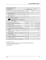
Page 67: ...e hydraulic oil return filter insert X X X 7 9 10 29 Replace breather X X 7 9 11 30 Crawler gear units Check or replace oil X O X X 7 9 12 31 Check that swing gear unit is securely fastened O O O 7 9...

Page 68: ...the ground Dispose of in compliance with regulations Oil change Run the engine until it reaches operating tem perature engine oil temperature approx 80 C Park the machine on a level surface Switch of...

Page 69: ...cold Danger of scalding from hot coolant Remove the cap 47 1 and check the water level The water level must be up to the overflow pipe 47 2 Top up with a mixture of 50 water and 50 antifreeze Water c...

Page 70: ...the water drain plug 48 2 from the cylinder block and drain coolant Flush the cooling system with clean water if necessary Re fit the drain plug to the engine and close the drain valve on the cooler...

Page 71: ...e fuel level using the fuel gauge 49 23 In order to prevent condensation from forming before the machine is next put into operation top up the fuel every day after use 50 1 Collect fuel when working o...

Page 72: ...rding to the ring 52 3 Close the shut off valve 52 1 on the water separator Unscrew the bottom part 52 2 clean the housing and the filter insert Check if the filter insert is damaged and replace if ne...

Page 73: ...parts for damage Replace damaged parts immediately 7 9 5 3 Cartridge maintenance interval Air filter main cartridge The air filter main cartridge must be replaced when during operation the filter clo...

Page 74: ...aged air filter cartridges as this may result in damage to the diesel engine Mount the air filter cartridge into the filter housing by slightly turning Mount cover with dust ejection valve to the bott...

Page 75: ...ons Checking the V belt tension without a tensioning device To check the tension press the V belt with your thumb in the middle of the greatest free length and measure the sag of the V belt Using medi...

Page 76: ...elt Slightly press the water cooler to the right and take out the V belt above the fan blade Mount new V belt and tighten in compliance with instructions Re mount the 2 fastening screws of the grill R...

Page 77: ...dentical Check the overlapping of the valve by moving the crankshaft by approx 20 in both directions The rocker arm must not move If the rocker arm moves the crankshaft must be turned further by one f...

Page 78: ...engine Unscrew the breather 60 1 Place suitable oil drip pans below the outlet Danger of scalding when hot oil is drained Unscrew the drain plug 60 4 from the hydraulic oil tank and drain oil into cl...

Page 79: ...outlet side with compressed air If necessary e g if there is oil in the cooler clean with cold cleaner or a steam jet appliance When cleaning with the aid of a steam jet appliance the cleaning area mu...

Page 80: ...screw off paying attention to the O ring 63 2 and the spring 63 3 Pull out the filter element 63 4 and dispose of in compliance with regulations Clean the filter bowl if required Check O rings 63 2 6...

Page 81: ...ely at the bottom Open the filler inspection plug 64 2 on the gear Open the drain plug 64 1 and collect the oil Flush out the gear with flushing oil if necessary Carefully re insert the drain plug wit...

Page 82: ...the hand grease gun via the grease nipple 65 1 Move crawler chain and check the crawler chain tension once more In the case of new rubber crawler chains check the sag on the first day of operation 2...

Page 83: ...the screws must again be checked after 100 operating hours The following points are prerequisites for an optimum bolted connection on the undercarriage and the uppercarriage The contact faces of bolts...

Page 84: ...ear is maintenance free Circulation lubrication provided by the hydraulic system 7 9 17 Windshield washer Top up the washer fluid storage tank 69 13 as required Add antifreeze when temperatures are ar...

Page 85: ...e side flap Disconnect first the battery ground cable then the positive cable Detach the clamping bracket 70 1 Lift out the battery Installing the battery Place the battery in the machine Secure with...

Page 86: ...le grease Seal off the air intake opening of the air filter system and the exhaust pipe opening 7 10 2 During shutdown When the machine is out of use for 6 months after this time all assemblies must b...

Page 87: ...ialist workshop Fault Possible cause Remedy 8 3 Machine is not driving 1 Engine damaged Check engine 2 Too little hydraulic oil in tank Top up hydraulic oil to recommended mark 3 Hydraulic pump has fa...

Page 88: ...n hose connections Replace O ring or seals 4 Insufficient operating pressure Re adjust or replace main pressure relief valves 8 7 Machine is working too slowly and hydraulic oil is becoming too hot 1...

Page 89: ...cables connections and fuses Examine wiper for mechanical damage replace wiper motor if necessary 3 Windshield washer system does not function Check water level Check cables connections and fuse Chec...

Page 90: ...8 Operating Problems TC29 84...

Page 91: ...orking floodlights rear boom F5 10 A Travel slow fast travel motion alarm F6 10 A Swing brake dozer blade F7 15 A Heater fan F8 15 A Windscreen washer F9 10 A Horn radio 15 F10 10 A Option 2nd control...

Page 92: ...wait approx 5 seconds before re entering it If 3 incorrect codes have been entered the system is disabled for 8 minutes Before leaving the machine in a workshop you should enter a 6 digit code and inf...

Page 93: ...times and goes out 3 Immediately press 2 3 4 5 6 7 your workshop code 4 Immediately press 1 until the green LED flashes 4 times and goes out 5 Immediately press 2 3 4 5 6 7 your workshop code again 6...

Page 94: ...9 Appendix TC29 88...

Page 95: ...s and points of lubrication according to overview of lubricating points and demonstration of these points on the machine Handing over the diesel engine operating instructions 2 Spare parts list Struct...

Page 96: ...ocket crawler gear units and hydraulic motor O O 22 Check smooth running of bottom and top rollers O O 23 Check bearing bushings and bolts of work equipment and re adjust free of clearance O O O Check...

Reviews: