background image

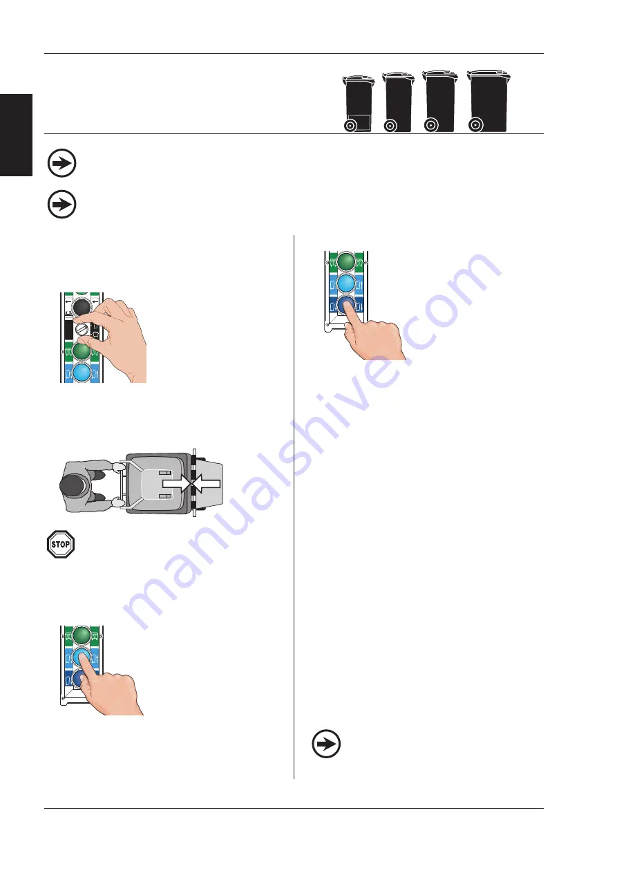
5) Remove the bin:

-

Press  the  dark  blue
DOWN button (H).

The  bin  lowers  to  the
ground.

-

Pull the bin out of the bin
lift  as  soon  as  the  wheels
touch the ground.

14

EN

E

N

3

 B

in

 l

if

o

p

e

ra

ti

o

n

37878

05-2017

ã

Terberg Machines B.V., IJsselstein, The Netherlands

All rights reserved. No part of this book may be reproduced, stored in database or retrieval system, or published, in any form or in any way, 

electronically, mechanically, by print, photoprint, microfilm or any other means without prior written permission from the publisher.

1) Switch  on  the  refuse  collection  vehicle's 

compactor body.

2) Select 2-wheel bins:

Set the rotary switch (E) to
2-wheel bins. 

[Or press the black button (K), this
can  be  done  on  both  button 
control stations. 

The  left-hand  LED  next  to  the 
2-wheel bin should light up.]

*

3) Roll the bin against and over the pick-up comb

(06).

4) Empty the bin:

Press the light blue UP but-
ton  (G),  on  the  side  of  the
lifting chair selected.

The bin will be lifted to the tip-
ping position and emptied.

If any refuse remains stuck in the bin, you can give it
an extra shake by keeping the UP button pressed.

3.4.1 2-wheel bins;

capacity 80 to 360 litres
according to EN 840-1

Chamberlain

Chamberlain

For manual loading, the safety arms (04) do
not need to be folded down.

Because in manual operation the bin security
switch is deactivated, great care must be
taken that the bin is located correctly on the
pick-up comb.

The optional DIN pick-up arms (18) must be
folded in.

3.4

Manual loading with the pick-up comb

[  ] * 

This text applies to the optional button control stations. See 'Important components' at the start of this chapter.

Only give an extra shake if there is a need for
this. Shaking takes time and causes extra
noise for the surrounding area.

Summary of Contents for OMNIDEKA

Page 1: ...phone 31 30 2100 600 Telefax 31 30 2100 610 Homepage www terbergmachines nl E mail info terbergmachines nl Translation of the original instruction Issue date 05 2017 The original Dutch version article code 37877 can be obtained from Terberg Please send a mail to info terbergmachines nl OMNIDEKA OMNIDEKA e ...

Page 2: ...ers 17 3 7 Loading using SMT Single Man Trade 18 3 8 Loading with DIN pick up arms optional 19 3 9 Shake function 2 wheel bins Green waste 20 3 10 Transport and travel positions 20 3 11 Diagnostic System 22 3 11 1 Level 1 Home screen messages 23 3 11 2 Level 2 Monitor 24 3 11 3 Level 3 Bin counter optional 25 3 11 4 Level 4 Configuration menu 25 3 11 5 Level 5 Settings 27 4 MAINTENANCE AND CLEANIN...

Page 3: ...ols used NOTE Additional information CAUTION If these instructions are not followed this may result in slight to average injury and or damage to the product or the environment WARNING If these instructions are not followed this may result in serious or fatal injury and or serious damage to the product or the environment The user manual has the following sections 1 Introduction A description of the...

Page 4: ...ick up arms optional 19 Chair lock mechanical optional 20 Taillights optional 21 Handle bar optional 4 EN EN 1 Introduction 37878 05 2017 1 1 Description of the bin lift system ã Terberg Machines B V IJsselstein The Netherlands All rights reserved No part of this book may be reproduced stored in database or retrieval system or published in any form or in any way electronically mechanically by prin...

Page 5: ...in any way electronically mechanically by print photoprint microfilm or any other means without prior written permission from the publisher 1 1 Description of the bin lift system Guidelines and standards 2006 42 EG EN 1501 1 EN 1501 5 2011 Weight 650 kg standard 685 kg with DIN pick up arms Noise level without bin container 61 dB A Noise level according EN1501 4 6 4 3 70 dB A Vibrations 2 5 m s2 O...

Page 6: ...reserved No part of this book may be reproduced stored in database or retrieval system or published in any form or in any way electronically mechanically by print photoprint microfilm or any other means without prior written permission from the publisher Terms of conformity This bin lift conforms to the current standards at the time of production It has been tested and checked on a rig in normal c...

Page 7: ...an cause problems Overweight bins containers should be removed from the bin lift system max lifting capacity 2 wheel bins 1700N 170kg max lifting capacity 4 wheel cont 5000N 500kg Check that the bin container is positioned cor rectly on the pick up comb before emptying it Let go of the bin container as soon as it is lifted It is expressly forbidden to manually assist the lifting cycle by hand Only...

Page 8: ... a higher capacity When dismantling disconnect the plugs and couplings from the vehicle Following a collision involving the bin lift system Terberg will need to assess whether it is still safe to use or first needs to be repaired Original or specified parts should always be used for repair or maintenance Do not stand under the bin lift or the bin container Repairs may only be carried out by qualif...

Page 9: ...retrieval system or published in any form or in any way electronically mechanically by print photoprint microfilm or any other means without prior written permission from the publisher General If it is noticed that the bin lift system does not work or has a fault while collecting refuse the workshop or service station must be informed immediately with a clear description of the defect Emergency st...

Page 10: ... lift bins automatically or semi automatically the green light shows a steady light again The sensors are checked during each automatic lifting operation When a sensor fault is identified the automatic lifting is switched off The RPD system is designed such that it is not activated by rain or snow When refuse snow or another object block the unobstructed view of a sensor the lifting chair will ris...

Page 11: ...eserved No part of this book may be reproduced stored in database or retrieval system or published in any form or in any way electronically mechanically by print photoprint microfilm or any other means without prior written permission from the publisher THIS PAGE INTENTIONALLY LEFT BLANK ...

Page 12: ...ation R H with integrated emergency stop 02 Button control station L H with integrated emergency stop 03 Diagnostic System 04 Safety arm 05 Lifting chair 06 Pick up comb 07 Locking plate 08 Bin security switch 09 Pedal arm cycle start switch 10 Position for RFID antenna 01 optional Country dependent The position of the control stations have been switched The Diagnostic System is mounted on the lef...

Page 13: ... lift system as a seat This is life threateningly dangerous When the bin lift system is in operation you may not reach into the lifting system this may cause a danger of injury It is forbidden to stand on the footboards while the refuse collection vehicle is reversing Make sure that you are visible to the driver of the refuse collection vehicle when it is reversing Before you start work you must c...

Page 14: ...eel bin should light up 3 Roll the bin against and over the pick up comb 06 4 Empty the bin Press the light blue UP but ton G on the side of the lifting chair selected The bin will be lifted to the tip ping position and emptied If any refuse remains stuck in the bin you can give it an extra shake by keeping the UP button pressed 3 4 1 2 wheel bins capacity 80 to 360 litres according to EN 840 1 Ch...

Page 15: ...container will be lifted to the tipping position and emp tied Because in manual operation the container security switch is deactivated great care must be taken that the container is located correctly on the pick up combs If any refuse remains stuck in the container you can give it an extra shake by keeping the UP button pressed 5 Remove the bin Press the dark blue DOWN button H The container lower...

Page 16: ...without prior written permission from the publisher The automatic function must be switched on for each side After emptying a 240 litre bin the pick up comb will be in too high a position with respect to an 80 120 litre bin By moving the 80 120 litre bin briefly before the start sensor the lifting chair will automatically descend to the right height In certain circumstances it may happen that a bi...

Page 17: ...ction vehicle s compactor body 2 Fold both safety arms 04 down horizontal 3 Select 4 wheel containers Set the rotary switch E to 4 wheel containers Or press the black button K this can be done on both button control stations The right hand LED next to the 4 wheel container should light up Both the lifting chairs will go to the correct height for loading 4 wheel containers 4 Switch on the automatic...

Page 18: ...ated in the left or right button control station Single man trade is only possible when 4 wheel containers are lifted with the pick up comb Emptying 4 wheel containers via DIN arms is not possible with the single man trade function because the container security switches do not operate then 5 Empty the container Press the light blue UP but ton G on one of the two button control stations The contai...

Page 19: ...on vehicle s compactor body 2 Select 4 wheel containers Set the rotary switch E to 4 wheel containers Or press the black button K this can be done on both button control stations The right hand LED next to the 4 wheel container should light up Both the lifting chairs will go to the correct height for loading 4 wheel containers 3 Fold out both DIN pick up arms 18 When opening the left hand pick up ...

Page 20: ... operated when the refuse collection vehicle is travelling along and also not when reverse gear is engaged Never stand on other parts of the bin lift and also never use them as a seat this is extremely dangerous TRANSPORT position For sufficient bottom clearance the lifting chairs must be set to the highest position with the optional pick up arms folded in and the optional footboards folded up whe...

Page 21: ... The Netherlands All rights reserved No part of this book may be reproduced stored in database or retrieval system or published in any form or in any way electronically mechanically by print photoprint microfilm or any other means without prior written permission from the publisher TRANSPORT TRAVEL HEIGHT LOADING Handle bar ...

Page 22: ...icle End of warranty date code 1003 This is the end date of the warranty period Historical alarms code 1004 A number of actions as well as faults are stored in the historical alarm list this can store up to 200 messages This list can be consulted during maintenance and when rectifying faults see also chapter 4 6 Trouble shooting section Alarm messages Time and date code 1005 Here you will find the...

Page 23: ...rieval system or published in any form or in any way electronically mechanically by print photoprint microfilm or any other means without prior written permission from the publisher Home screen messages TERBERG OMNIDEKA TIME HH MM SS TERBERG OMNIDEKA DATE DD MM YY Level 1 Level 2 After switching ON the bin lift system you go automatically to Level 1 Home screen messages See next pages for the leve...

Page 24: ...00 4 0 AI00 5 0 AI00 6 0 AI00 7 0 AI01 0 0 AI01 1 0 AI01 2 0 0 0 0 AI01 3 0 AI01 4 0 AI01 5 0 POSITION R H 0000 push 2x input 0 0 0 1 input 0 2 0 3 input 0 4 0 5 input 0 6 0 7 input 1 4 1 5 input 1 2 1 3 input 1 0 1 1 AI01 6 0 AI01 7 0 input 1 6 1 7 Status DIGITAL output 000000000000000 DIG OUT 0 _ _ 0 15 POSITION L H 0000 DIG OUT 0 _ _ 16 31 000000000000000 000000000000000 DIG OUT _ 1 _ 0 15 DIG ...

Page 25: ...1 2 ENTER CODE ENTER CODE 1 2 3 CONTAINER DAY COUNTER L H 000 R H 000 TRADE 00 4 W DIN 00 RESET 0 confirm with change with RESET NO CONTAINER COUNTERS confirm with change with confirm with change with The display shows Number emptied 2 wheel bins that day Number emptied 4 wheel containers and 4 wheel containers with DIN arms RESET YES Question confirm with change with TCA PNP V1 0 ENTER CODE ENTER...

Page 26: ...with confirm with change with confirm with change with confirm with change with 01 EMERGENCY 1 STOP DATE DD MM TIME HH MM with keys you can display the next previous message ENTER CODE ENTER CODE ENTER CODE ENTER CODE DATE DD MM YY TIME HH MM SS 0 1 0 1 0 0 1 0 0 5 confirm with change with confirm with change with confirm with change with confirm with change with system date and GMT time view END ...

Page 27: ...NGS SMT STANDBY POS POSITION 00 0 SMT STANDBY POS POSITION 0 SMT STANDBY POS POSITION 0 0 SMT STANDBY POS POSITION 0 0 0 MONITOR push 3x SMT LIFT HEIGHT POSITION 00 0 confirm with change with confirm with change with confirm with change with SMT STANDBY POS POSITION 00 0 with keys you can display the next previous message SMT LIFT HEIGHT SMT LIFT HEIGHT SMT LIFT HEIGHT confirm with change with con...

Page 28: ...0 0 MONITOR push 3x confirm with change with confirm with change with confirm with change with REVERSE RAISE POSITION 00 0 Raise lifting chairs during reverse Travel height push 3x SETTINGS AUTO SWITCH 4W 2W SETTINGS AUTO SWITCH 4W 2W OPTION ON AUTO SWITCH xxxxxxx OPTION ON AUTO SWITCH xxxxxxx OPTION xxx MONITOR push 3x confirm with change with Automatically change over from 2 to 4 wheel and or fr...

Page 29: ...eactivate the variable shake mode ENABLED Variable shake mode active DISABLED Standard shake mode active VARIABLE SHAKE MODE VARIABLE SHAKE MODE ENABLED DISABLED with keys you can display the next previous message with keys you can display the next previous message with keys you can display the next previous message TOTAL SHAKES SW 1 TOTAL SHAKES SW 1 TOTAL SHAKES SW 1 0 x 0 0 x 00 x confirm with ...

Page 30: ...change with LIFTER SPEED UP SPEED 2W 100 2 wheel bins UP and DOWN SPEED push 8x 0 0 0 0 0 0 LIFTER SPEED DOWN SPEED 2W 100 DOWN SPEED 2W DOWN SPEED 2W DOWN SPEED 2W confirm with change with confirm with change with confirm with change with LIFTER SPEED DOWN SPEED 2W 100 0 0 0 0 0 0 When exceeding the max or min value the most recently set value appears Max value 100 Min value 50 SETTINGS N6 SENSOR...

Page 31: ...eserved No part of this book may be reproduced stored in database or retrieval system or published in any form or in any way electronically mechanically by print photoprint microfilm or any other means without prior written permission from the publisher THIS PAGE INTENTIONALLY LEFT BLANK ...

Page 32: ...ly ã Terberg Machines B V IJsselstein The Netherlands All rights reserved No part of this book may be reproduced stored in database or retrieval system or published in any form or in any way electronically mechanically by print photoprint microfilm or any other means without prior written permission from the publisher General Before starting maintenance cleaning or repair work the following points...

Page 33: ...a The 4 greasing nipples for the main axles can be reached with the chairs in the tipped position Press the emergency stop button and support the chairs safely against lowering again when working under the chairs hoist props etc The 4 greasing nipples for the lifting cylin der axles can be reached with the chairs in the lowest position The top one via the side wall The catcherbar mechanism is prov...

Page 34: ...print photoprint microfilm or any other means without prior written permission from the publisher First carry out the weekly maintenance Container lock Check the clamp opening between the pick up comb 06 and the locking plate 07 see the illu stration below This must be done with the lifting chair in the highest position Measure between the left and right tooth and the locking plate The horizontal ...

Page 35: ...no more than 10 mm Grip the lifting chair with two hands and try to turn it vertically to the left see fig 4 4b and determine distance X1 Then rotate the chair to the right and determine distance X2 The sum of these two measurements may be no more than 5 mm Do the same with the other lifting chair Pick up comb tipping angle The tipping angle has been set ex factory If the pick up combs do not make...

Page 36: ... bar The lifting pressure of both lifting chairs is monitored by pressure sensors The lifting pressure can be read off on the Diagnostic System see chapter 3 par 3 11 2 Hydraulic hoses Check the production date of the hoses The hydraulic hoses must be replaced after 4 years in service This must be done at the latest 6 years after the production date shown on the hose ferrule Electrical wiring Chec...

Page 37: ...the working of these sonar sensors DIN pick up arms and chair lock mechanical X X X Check the chair lock when opening the L H DIN pick up arm Check that the fall down locks close in the tilted position 4 2 Instruction and safety decals X X X Damaged instruction and safety decals must be replaced immediately Lubrication X X X Individual greasing points apply grease 1 cc Greasing system administer 5...

Page 38: ...Additional information see paragraph Carried out Pick up teeth X Check the pick up teeth for wear Play in bearings X Check the bin lift for excessive wear in the bearings 4 4 Tipping angle pick up comb X Readjust if necessary 4 4 Lifting speed X Check the cycle time of the bin lift 4 4 Pressure in hydraulic system X Check the working pressure of the hydraulic system 4 4 Hydraulic hoses X Check the...

Page 39: ...and pin 2 Bin lift does not operate display text EMERGENCY STOP All emergency stop switches on the vehicle 24V supply on pin 12 normal safe situation of the 16 pin socket box Bin lift does not operate in automatic mode and or 4 wheel container recognition does not operate If the ultrasonic sensors are free of dirt Bin lift does not operate there is a certain alarm message on the display Check the ...

Page 40: ...010 Normal message during start up in the morning Please perform a zero adjust sequence by holding down the R H up and down button simultaneous ly in domestic mode for a few seconds until the bin lift moves up automatically 08 LOW SPEED CHECK OIL SUPPLY L H L H chair is moving up too slow in automatic mode it takes too much time before half height position is reached Check oil supply from the truc...

Page 41: ... the bin is removed the error will be reset Check for mechanical axial and radial play from the position sensors or adjoined bearings Check the position sensor s Check the cables from the position sensors Check the analogue values from the position sen sors analogue input 00 2 and 00 3 always higher than 100 lower than 900 Recalibrate the position sensors 20 ERROR TRADE SENSOR L H L H side trade 4...

Page 42: ... amount of bins emptied This message will appear on the screen to inform the user there is something wrong with the battery or the truck is not charging the battery anymore The bin lift will stop working to prevent damage to the battery and to make sure the truck engine can still start Charge the batteries by starting the engine Check the power supply or batteries 29 PICKUP ARM N7 ERROR L H L H pi...

Page 43: ... CAN connection Electric pressure weighing systems do not use this alarm nr They use alarm nr 116 37 TRADE CONTAINER TOO HEAVY An optionally mounted weighing system sends out a command to stop the bin lift because the contai ner is too heavy This stop signal can be given over conventional identification signals or over Clean Open CAN connection Electric pressure weighing systems do not use this al...

Page 44: ... please check footboards footboard sensors and signals from the refuse body 48 WAIT WEIGHING NOT READY L H Weighing systems VDH9013 TMDW9009 TMDW9004 TMDW8010 L H side of weighing system is busy calculating not ready to start a new weighing cycle Remove bin and wait a few seconds before applying a new bin If this message is continuously on the screen please check the weighing system 49 WAIT WEIGHI...

Page 45: ... the user There is a status check on the working of the ultrasonic sensor With the bin lift at pickup height the sensor always has to see the bin approaching the bin lift once the bin is 1 meter from ground so above sensor level it should not see the bin anymore If the area protection sensor or cable is broken or the sensor is blocked by dirt or snow this sequen ce is not possible and the bin lift...

Page 46: ... is sending a signal to the bin lift that it must wait in the tipped position until the washing is fully done Wait until the bin washing cycle is completed 63 WASHING BUSY R H Bin lifts with washing systems only R H lifter is in the tipped position and washing is busy Washing system is sending a signal to the bin lift that it must wait in the tipped position until the washing is fully done 64 WASH...

Page 47: ... down movement is possible First try to correct the tilting position 76 MOVE STOP TRD CYLINDER ERROR 4 Wheel trade container mode active Bin lift is below 50 position and tilting of L H or R H chair is not in a safe position only down movement is possible First try to correct the tilting position 77 DE3 IN TRADE CALIBRATION ACTIVE OmniDEKA bin lift with a 2 position switch instead of a push button...

Page 48: ...ck the magnet from position sensor HS1 Check cables and connectors to HS1 91 LH HS2 CHAIR ERRATIC READING A position sensor difference error caused by position sensor HS2 on the L H side Linearity check This is a timer based interval check with the bin lift in motion it checks the old position value and the current position value If the difference in position is too big this event is remembered in...

Page 49: ...hair this message will show on the display and the bin lift will stop lifting when it has fully passed the weighing window This is to avoid the bin with weight will reach the tipped position 106 R H WINDOW READY MOVE CHAIR DOWN Only during pressure weighing calibration mode active on R H side If you perform the max weight calibration reference weight on the chair this message will show on the disp...

Page 50: ...GH L H Oil pressure too high for the L H chair lifting 2 wheel domestic bins The bin lift will stop The bin applied to the bin lift is too heavy An object or debris is blocking the bin lifts movement 113 PRESSURE TOO HIGH R H Oil pressure too high for the R H chair lifting 2 wheel domestic bins The bin lift will stop 114 PRESSURE TOO HIGH TRADE CONTAINER Oil pressure too high for lifting a 4 wheel...

Page 51: ...he bin lift speed is corrected to a lower speed to prevent damage and dangerous situations 128 SMT STOP HIGHER THEN WEIGHING START Stop position of single man trade SMT stop is inside the pressure weighing window which result in a failure in calculating the bin weight This message is displayed for correction of the weighing start position to a higher position as the stop SMT position 129 FOOTBOARD...

Page 52: ...ift speed is changed in RunWin the speed which is set by the customer has to be dis abled When the service has disabled this setting this message appears on the SCB10 display As soon as the power is switched OFF and ON or the service engineer has enabled the customer speed setting with RunWin this message will be erased 139 HYDRAULIC WEIGHING IS OFF OmniDEKA bin lift Message which will be displaye...

Reviews: