background image


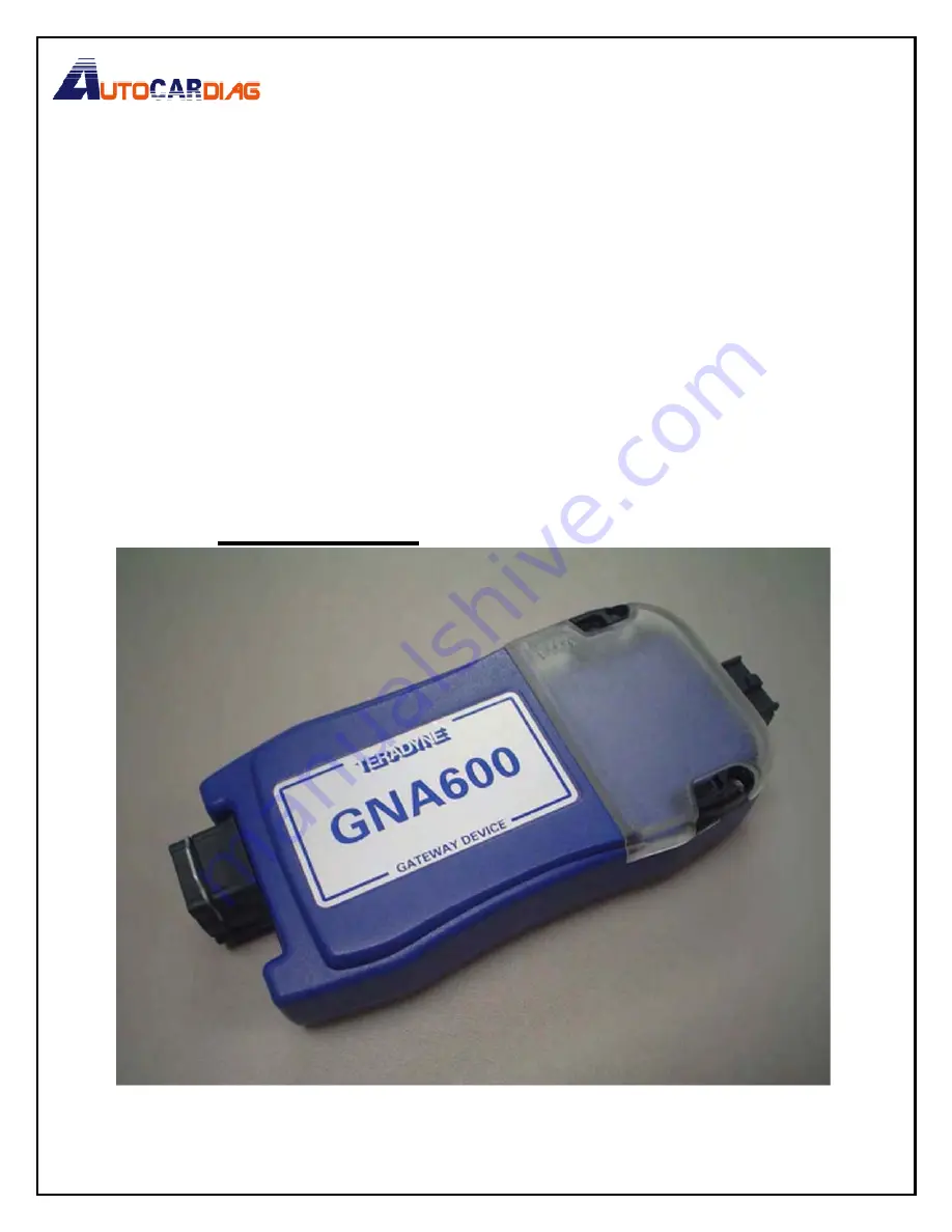
TERADYNE 

GNA600 

GATEWAY DEVICE 
USER GUIDE FOR 

HONDA VEHICLES 


© 2008 American Honda Motor Co., Inc. – All Rights Reserved 

AST 39880 (080

7

www.autocardiag.com

E-mail:[email protected]

Skype:Marshall.obd2

Whatsapp:86-13476108995

www.autocardiag.com

Summary of Contents for GNA600

Page 1: ...CE USER GUIDE FOR HONDA VEHICLES 2008 American Honda Motor Co Inc All Rights Reserved AST 39880 0807 www autocardiag com E mail autocardiag gmail com Skype Marshall obd2 Whatsapp 86 13476108995 w w w...

Page 2: ...oftware 11 5 SETUP 12 5 1 Before You Start 12 5 2 Setup Basics 12 5 3 Connection With the USB PC Interface Cable 13 5 4 Connection With an Ethernet Cable 13 6 UPDATING CONTROL UNITS MODULES 15 6 1 Ove...

Page 3: ...C to be useful How to Resolve Radio TV Interference Problems This booklet is available from the U S Government Printing Office Washington DC 20402 Stock 004 000 00345 4 1 2 Use of This Equipment in Ca...

Page 4: ...overheat Take care to arrange the cord so that it will not be tripped over or pulled accidentally 7 Always unplug the equipment from the electrical outlet when not in use Never use the cord to pull t...

Page 5: ...maintenance and cleaning operations refer to the Care and Maintenance section Use only a well diluted mild non abrasive cleaning agent applied by using a soft lint free cloth DO NOT allow the GNA600...

Page 6: ...the functions of the HIM Honda Interface Module but with additional capabilities The GNA600 is easiest to use with a wired USB connection but it can also be used with an Ethernet connection Here are t...

Page 7: ...Unit 5 Power Supply Cord 6 Trigger Switch Adapter Block Yellow 7 PC Interface Adapter Block Blue 8 Trigger Switch 9 256 MB PCMCIA Memory Card These are optional parts that can be purchased separately...

Page 8: ...splay diagnostic data on the PC screen DLC Cable TDS35541 433 Connects the GNA600 to the vehicle s 16 pin DLC Power Supply Unit TDS6067801 0 Provides A C power to the GNA600 when it is not connected t...

Page 9: ...gger Switch TDS35541 359 When it is connected to the Trigger Switch Adapter Block TDS35541434 the Trigger Switch allows the GNA600 to update control units modules in Storage Mode without a PC Not all...

Page 10: ...th the HDS software package and can be installed according to the instructions provided by the software distributor The GNA600 can be used with both HDS software and Control Module CM Update software...

Page 11: ...0 This does not indicate a connection to a vehicle The GNA600 can be selected as the default vehicle interface during installation of the HDS software or from the setup screen After you select the GNA...

Page 12: ...d as the default vehicle interface during installation of the Control Module CM Update software or from the setup screen The LED patterns seen on various screens during use of the CM Update software s...

Page 13: ...fully automatic if you have the correct drivers from the HDS software installed use the USB PC Interface Cable and carefully follow the set up instructions If you use an Ethernet cable you must do a m...

Page 14: ...ble To use an Ethernet connection you must configure the network adapter on the PC to a static address and use a straight through Ethernet cable not supplied You must also connect the PC Interface Ada...

Page 15: ...2 16 0 1 with a subnet mask of 255 255 255 0 Use an address that does not conflict with other network settings on that PC No gateway or DNS settings are required Once the address is set restart the PC...

Page 16: ...n enhanced to show the progress during the update as well as showing on screen instructions and the LED patterns you will see on the GNA600 The CM Update software can be used in Pass thru Mode or Stor...

Page 17: ...hown to the right the CM Update software is launched from the Windows Start menu To do control unit module updates the latest HDS software must be installed see section 4 A S T 3 9 8 8 0 0 8 0 7 16 of...

Page 18: ...GNA600 LED patterns see section 7 3 1 Connect the USB PC Interface Cable to the iN Workstation and to the GNA600 From the Updating Honda Control Modules main screen select Pass thru Mode 2 Connect th...

Page 19: ...0 4 Select the vehicle system that you are updating then click the Check Mark on the right side of the screen 5 Verify that the Program ID and the Program Part No are for the system you selected in st...

Page 20: ...pdate by Program ID and Program Part No Make sure this corresponds with any information provided in the service bulletin for the update you are doing Click on Yes to continue The CM Update software lo...

Page 21: ...8 0 0 8 0 7 2 0 o f 3 0 7 Click on the Check Mark to begin the control unit module update NOTE On non CAN vehicles the update can take 15 to 30 minutes CAUTION To avoid ECM PCM damage do not interrupt...

Page 22: ...completed turn the ignition switch to LOCK 0 and then back to ON II within 60 seconds 9 Once the software verifies that the control unit module has been successfully updated click on Yes to update an...

Page 23: ...pdating Honda Control Modules main screen select Storage Mode and follow the on screen instructions 2 Connect the DLC Cable to the GNA600 and to the vehicle s DLC You don t need to turn the ignition s...

Page 24: ...eck Mark 7 Confirm the control module update by Program ID and Program Part No Make sure this corresponds with any information provided in the service bulletin for the update you are doing Click on Ye...

Page 25: ...h button 11 The yellow 1 LED blinks and the green 2 LED stays on This indicates that the control unit module is being updated NOTE On non CAN vehicles the update can take 15 to 30 minutes CAUTION To a...

Page 26: ...setup details are correct 6 Reboot the computer and restart the software 7 Completely disconnect the GNA600 from the computer the vehicle and power supply and reconnect according to section 5 2 7 2 C...

Page 27: ...from the control unit module OFF ON OFF Ready for updating BLINKS ON OFF Updating is in progress ON OFF OFF The control unit module has been updated Turn off the ignition switch BLINKS OFF OFF The ign...

Page 28: ...cleaners or any type of polish If dust or other particles get on the GNA600 Unit lightly brush the unit off with a soft lint free cloth 8 2 Cable Care Always return the cables to their appropriate sto...

Page 29: ...t 15 to 85 RH non condensing Storage 20 C to 70 C 4 F to 158 F at 15 to 85 RH non condensing Standards and Regulatory The GNA600 fulfills the requirements of the CE marking Compliances scheme and UL20...

Page 30: ...ions in any software used with the GNA600 relating to required cable connections Failure to follow these instructions can result in permanent damage to the GNA600 Such damage is not covered by this wa...

Page 31: ...ed or otherwise regarding the accuracy and completeness of this document and shall in no event be liable for any loss of profit or any other commercial damage including but not limited to special inci...

Reviews: