


GENERAL
These operationg instructions are intended to help you install and
operate the drive. For trouble free service, proper installation and
operation are essential. Additionally, these instructions contain
important recommendations on maintenance.
Before shipment, every SEW-Eurodrive gear unit is tested,
checked and properly packed. However, please inspect the drive
immediately upon arrival for shortage or transit damage. Note the
damage or shortage on the freight bill of lading and file a claim
with the carrier. Also, notify SEW-Eurodrive of the shortage or
damage.
LUBRICANTS
All gearmotors and gear reducers are supplied with the correct
grade and quantity of lubricating oil for the specified mounting po-
sition. Exceptions include reducers shipped without input assem-
blies. The recommended lubricants are found on page 2.
LONG TERM STORAGE
If the drive is not installed immediately, it should be stored in a dry,
protected area. If the drive is to be stored for an extended period of
time and was not ordered from SEW for long term storage, contact
your nearest SEW assembly plant for information on Long Term
Storage or request
Document #2115
.
Drives which are used for standby service should be stored as a
sealed gearcase.
INSTALLATION OF COMPONENTS ON DRIVE SHAFTS
Do not hammer on the shafts. Hammering can cause brinelling of
the reducer’s bearings shortening the bearing life. We recommend
heating the components to approximately 175°F (when possible)
and sliding them on the shaft. This will reduce possible damage to
the reducer’s bearings.
Document #2116
.
For both standard and metric SEW shaft tolerances, refer to the
SEW Catalog or request
Document #2154.
Shaft couplings should be properly aligned to prevent vibration,
coupling wear, and premature failure of the shaft bearings.
To prevent the output shaft and bearings from being subjected to
excessive loads, the maximum overhung load, as shown in
SEW-Eurodrive catalogs, should not be exceeded. Please consult
our engineering department if the load may exceed the recom-
mended figure given or where there are combined radial and axial
loads. In such cases, the exact operating conditions must be stated
including speed, direction of rotation, position, magnitude and di-
rection of the external radial and axial loads being applied.
SHAFT MOUNTED REDUCERS
SEW-Eurodrive supplies the recommended hollowshaft mount-
ing paste with every hollowshaft reducer. The mounting paste is to
be applied on the keyed output shaft. The mounting paste is to aid
in the prevention of rusting and fretting corrosion between the re-
ducer hollowshaft and the shaft of the driven machine. The
mounting paste will aid in shaft removal when necessary.
Warning!
Always ensure exposed, rotating parts are properly
covered to ensure safety.
For additional information on shaft mounted reducers, drive shaft
configuration and tolerances, refer to the SEW-Eurodrive Catalog
or request
Documents #2201 and #2202
.
INSTALLATION AND OPERATION
The drive installation site should be selected to ensure:
•
Ambient temperatures below 40°C (104°F).
•
Unimpeded flow of air to the motor and variable speed units.
•
Accessibility to the drain, level and breather plugs.
•
Adequate space for the removal of brakemotor fanguard for brake
adjustment and maintenance.
The drive unit should be mounted on a flat, vibration damping, and
torsionally rigid structure. Careful alignment is critical. Mount-
ing to an uneven surface will cause housing distortion. The flat-
ness tolerance of the supporting surface should not exceed:
•
For gear units size 80 and smaller — 0.004 inch.
•
For gear units above size 80 — 0.008 inch.
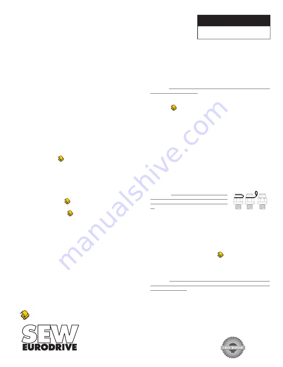
For transportation, the units are sup-
plied with the breather plug already
mounted. After the unit is installed, the
black rubber seal located on the
breather MUST BE REMOVED (Fig.
1).
In addition, the oil level should be
checked.
Remove the plated
(non-painted) oil level plug. The oil level
is correct when the surface of the oil is level with the lowest point
of that tapped hole, the exception is S37. Units W20 and W30 are
sealed in any position.
After installation, the actual mounting position should be con-
firmed against the mounting postion shown on the gear reducer
nameplate. Adequate lubrication is only guaranteed if the unit is
mounted in the specific nameplated mounting position.
Refer to the SEW Catalog or request
Document
#2111,
#2112, #2113, or #2114 (R, F, K, orS, respectively)
if a specific
mounting position diagram is needed.
MAINTENANCE
Warning!
Always ensure equipment is secure and electrical
power is off before removing or performing maintenance on
the drive assembly.
Oil levels and oil quality should be checked
at regular intervals, determined by usage and the environment.
Grease and oil should be changed per the recommendations on
page 2. Check coupling alignment, chain or belt tension, and
mounting bolt torque periodically. Keep the drive relatively free
of dust and dirt.
OPERATING INSTRUCTIONS
01 805 52 US
Gearmotors and Gear Reducers
Fig. 1
For additional information, call the SEW FAXline, 1-800-601-6195, and request document number shown.
SOUTHEAST MANUFACTURING
& ASSEMBLY CENTER
1295 Old Spartanburg Hwy, Lyman, SC 29365
(864) 439-7537
Fax: (864) 439-7830
MIDWEST ASSEMBLY CENTER
2001 West Main Street, Troy, OH 45373
(937) 335-0036
Fax: (937) 222-4104
WEST COAST ASSEMBLY CENTER
30599 San Antonio Road, Hayward, CA 94544
(510) 487-3560
Fax: (510) 487-6381
SOUTHWEST ASSEMBLY CENTER
3950 Platinum Way, Dallas, TX 75237
(214) 330-4824
Fax: (214) 330-4724
EAST COAST ASSEMBLY CENTER
200 High Hill Road, Bridgeport, NJ 08014
(856) 467-2277
Fax: (856) 330-4724
Summary of Contents for LM1014
Page 5: ...5...
Page 6: ...6...
Page 7: ...7...
Page 11: ...11 LM Control Box Overlay...
Page 20: ...20...
Page 21: ...21 LM Machine PARTS View...
Page 24: ...24 LM 2x Back gauge Crank Assembly...
Page 26: ...26 LM 2x Back gauge Pointer Assembly...
Page 28: ...28 LM 2x Back gauge Drive Assembly...
Page 29: ...29 LM 2x Back gauge Arm Assembly...
Page 31: ...31 LM Four Foot Squaring Arm...