Tennsmith LM1014 Operation, Parts & Maintenance Manual Download Page 37

SEW-Eurodrive motor brakes can be connected in a number of different
ways. In order to connect the brake for each application, it is important to
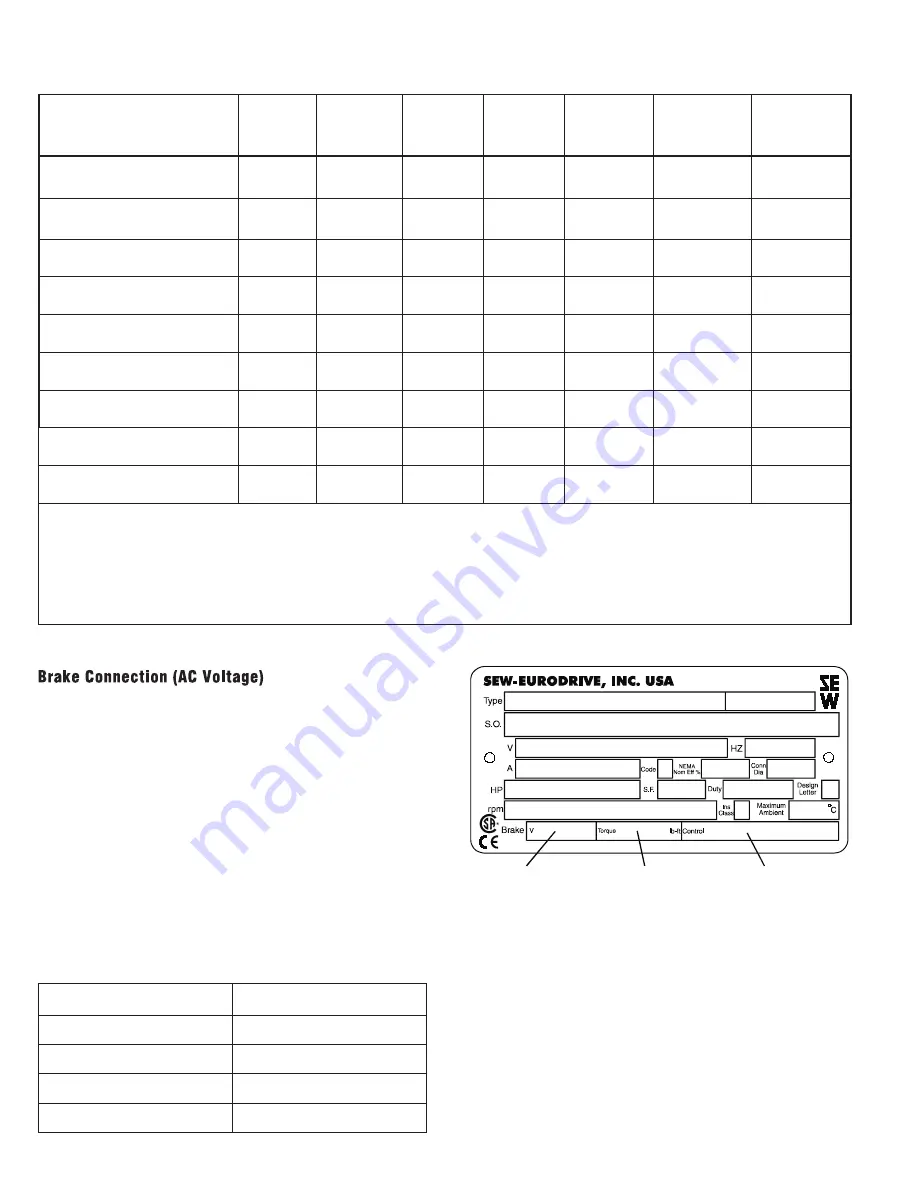
refer to the data on the motor nameplate that describes the brake system.
The brake fields are:  brake voltage, brake torque and brake control.

This operating instruction covers AC brake voltages with the following
brake control components. If the brake voltage is DC, or if the brake con-
trol components differ from those listed below, an additional operating
instruction must be consulted for connection information.

SEW-Eurodrive fail-safe mechanical brakes are DC controlled. Stan-
dardly, a brake rectifier (halfwave) is provided to convert the AC line
voltage to the DC voltage required to drive the brake. 24VDC brakes do
not include a rectifier. When voltage (V

B

) is applied to the brake, it will

release. When voltage (V

B

) is removed from the brake, it will set. The

brake rectifier can be wired either for normal brake reaction time (set-
ting, stopping) or fast brake reaction time. The fast brake reaction will set
the brake more quickly which will provide a shorter and more repeatable
stopping distance. There are two basic types of brake rectifiers, BG and

BGE. The BG brake rectifier is standard on motor sizes DT71 - DT100.
The BGE rectifier is standard on motor sizes DV112 - DV225. The BGE
rectifier can be ordered with motor sizes DT71 - DT100 and will provide
faster brake release times allowing the motor to cycle more frequently.

The wiring diagrams for brake connections are located on the inside of
the motor conduit box lid. The brake will release and allow the motor to
rotate when the nameplate AC brake voltage V

B

is supplied to the brake

rectifier terminals. There are certain cases where the brake rectifier can
receive its voltage from the motor's terminal block, meaning that when
power is applied to the motor it will simultaneously release the brake and
start the motor. See page 3 for this description.

Brake Coil Resistance

Motor Frame

DT71-80

DT80

DT90-100

DT100

DV112-132S

DV132M-160M

DV160L-225

Brake Size

BM(G)05

BM(G)1

BM(G)2

BM(G)4

BM(G)8

BM15

BM30/31/32/62

Brake Torque (lb-ft)

0.89 - 3.7

4.4 - 7.4

3.7 - 14.8

17.7 - 29.5

7.00 - 55.3

18.4 - 110.6

36.9 - 442.5

BRAKE VOLTAGE

R

B

(

)

R

B

(

)

R

B

(

)

R

B

(Ω

)

R

B

(

)

R

B

(

)

R

B

(

)

AC (to rectifier V

B

)

DC

R

T

(

)

R

T

(

)

R

T

(

)

R

T

(

)

R

T

(

)

R

T

(

)

R

T

(

)

24

4.3

3.8

3.3

7

1.6

0.8

0.7

13.2

11.8

10.3

8.2

8.2

5.0

5.3

105-116

48

17.1

52.5

15.2

47.0

13.3

40.9

10.7

32.7

6.2

32.7

3.1

20.1

2.8

21.1

186-207

80

54.0

166

48.1

149

42.1

129

33.8

103

19.6

103

9.8

63.5

8.9

66.7

208-233

96

68.0

209

60.5

187

53.0

163

42.5

130

24.7

130

12.4

80.8

11.2

84.0

330-369

147

171

525

152

470

133

409

107

327

62

327

31.1

201

28.1

211

370-414

167

215

661

191

591

168

515

134

411

78.1

411

39.2

253

35.4

266

415-464

185

271

832

241

744

211

649

169

518

98.3

518

49.3

318

44.6

334

465-522

208

341

1047

303

937

266

817

213

652

110

577

62.1

401

56.1

421

Voltage AC - The voltage shown is the nameplate AC brake voltage supplied to the brake rectifier.

DC - The voltage shown is the effective DC voltage required by the brake coil.  The measured  voltage from

the rectifier will be 10-20% lower than that shown.

Brake Coil Resistance - values must be measured with the brake coil disconnected from the rectifier.

R

B

-

Accelerator coil resistance in

, measured from the red to the white brake coil wire.

R

T

-

Fractional coil resistance in

, measured from the white to the blue brake coil wire.

Brake Control (Rectifier)

Part Number

BG1.5

825 384 6

BG3.0

825 386 2

BGE1.5

825 385 4

BGE3.0

825 387 0

Brake Voltage

Brake Torque

Brake Control

2

Summary of Contents for LM1014

Page 1: ...4 Performance F MODEL LM1014 MECHANICAL SHEAR OPERATION PARTS MAINTENANCE MANUAL Model Purchased From Serial Date Received 6926 Smithville Hwy McMinnville TN 37110 931 934 2211 Fax 931 934 2220 www te...

Page 2: ...AND INSTUCTIONS 4 9 INSTALLATION 10 OPERATING INSTRUCTIONS 11 13 BLADE CLEARANCE ADJUSTMENT 14 BLADE ROTATION REPLACING 15 16 BACKGAUGE INFORMATION 16 HOLDDOWN INFORMATION 17 SHEET SUPPORT SYSTEM INFO...

Page 3: ...iod Additionally we agree that for a period of thirty six 36 months from date of delivery to replace component parts proving defective within the stated period All warranty claims are made F O B our p...

Page 4: ...he following safety decals are attached to the LM Shear If you do not locate all of the decals please contact Tennsmith to replace any missing or unreadable safety labels NEVER operate this machine wi...

Page 5: ...5...

Page 6: ...6...

Page 7: ...7...

Page 8: ...this machine is properly wired and grounded to conform to the National Electric Code The connection of this machine to the power source should only be made by and inspected by a qualified electrician...

Page 9: ...accessible 9 Do not remove guards unless required to service the machine Replace all protective covers prior to operation 10 Always wear gloves to protect your hands when handling the shear blades 11...

Page 10: ...r and leveled before operating Check the level of the shear with a machinist level both along the length and depth of the machine Use the leveling screws 35 provided with the machine to achieve proper...

Page 11: ...11 LM Control Box Overlay...

Page 12: ...utton is located under the Push Pull switch on the panel It is designated 3 on the previous page The Jog function allows the operator to engage the motor and move the cutter head of the shear up or do...

Page 13: ...select run on switch 2 Jog Run Switch and select Cont on the stroke selector switch With this mode the cutter head will repeat continuously a full cycle until the operator releases his foot from the f...

Page 14: ...ight 2 Loosen the four table bolts 43 again reasserting only a slight amount of pressure back to each one 3 The table positioning screws 20 located at both ends of the table are the means used to achi...

Page 15: ...ing pressure of the hold down pads while the assembly is removed from the shear Remove the top sheet metal cover from the top of the hold down and insert the compression bolts inside the hole mounts o...

Page 16: ...inches of travel To verify the back gauge was not disturbed during shipping rotate the hand wheel bringing the gauge into contact with the bottom blade The display should now read zero If the display...

Page 17: ...nnect the power to the machine 3 Remove the sheet metal cover on the top of the hold down 4 To raise the height of the hold down pad use two 7 8 wrenches unlock the two nuts that are locked and positi...

Page 18: ...he two flow controls on the sheet support air valve The pressure to the system is regulated by the Filter Regulator unit that the air supply connects to Generally 80 psi on the regulator will give con...

Page 19: ...MACHINE HAS BEEN TURN OFF WHEN APPLING LUBRICATES Also each month apply grease to the zerk fitting of the support bearings 53 of the drive linkage shaft 55 Otherwise periodic lubrication with a good...

Page 20: ...20...

Page 21: ...21 LM Machine PARTS View...

Page 22: ...1014017 SPACER SLEEVE HOLD DOWN 6 18 1014018 SCREW GIBB ADJ FRONT 6 19 1014019 NUT SCREW GIBB ADJ FRONT 6 20 1014020 BOLT TABLE ADJ 4 21 1014021 SCREW CONTROL BOX MOUNT 4 22 1014022 SIDE PANEL RIGHT 1...

Page 23: ...ECTRIC GEAR MOTOR 1 57 1014057 BOLT MOTOR AND GEAR BOX MOUNTING 4 58 1014058 KEY SHAFT GEAR BOX 1 59 1014059 BOLT ARM AND PIN ASSEMBLY GEAR BOX SHAFT 1 60 1014060 ARM AND PIN ASSEMBLY GEAR BOX FRONT L...

Page 24: ...24 LM 2x Back gauge Crank Assembly...

Page 25: ...R SPROCKET BRACKET MOUNTING 12 152 20151 LOCK WASHER BOLT IDLER SPROCKET BRACKET 12 153 20153 BRACKET IDLER SPROCKET MOUNTING 1 174 20174 BOLT HANDLE MOUNTING 1 175 20175 HANDLE CRANK 1 176 20176 CRAN...

Page 26: ...26 LM 2x Back gauge Pointer Assembly...

Page 27: ...ING 1 156 20156 RETAINER BEARING MOUNTING 2 157 20157 TEFLON PIN POINTER BLOCK 2 158 20158 SPRING POINTER BLOCK 2 159 20159 SET SCREW POINTER BLOCK 2 160 20160 NUT SET SCREW POINTER BLOCK 2 161 20161...

Page 28: ...28 LM 2x Back gauge Drive Assembly...

Page 29: ...29 LM 2x Back gauge Arm Assembly...

Page 30: ...L AND ROLLER ASSEMBLY 2 115 20115 SET SCREW BRACKET MONTING ROLLER ASSY 8 116 20116 JAM NUT BRACKET MOUNTING ROLLER ASSY 8 117 20117 BRACKET ROLLER ASSEMBLY 2 118 20118 CLAMP CHAIN LOCK ROLLER ASSEMBL...

Page 31: ...31 LM Four Foot Squaring Arm...

Page 32: ...STUD LOCK HANDLE BLOCK SQ ARM 1 212 40212 TEFLON STUD LOCK HANDLE BLOCK SQ ARM 1 213 40213 STOP BLOCK SQUARING ARM 1 214 40214 SET SCREW STOP BLOCK 1 215 40215 PIVOT BLOCK STOP BLOCK 1 216 40216 STUD...

Page 33: ...0199 WASHER RACK MOUNTING 2 200 FS10200 TEFLON WASHER RACK MOUNTING 2 201 FS10201 STRIPPER BOLT RACK MOUNTING 2 202 FS10202 BRACKET AIR CYLINDER MOUNTING 2 203 FS10203 LOCK WASHER AIR CYLINDER MOUNTIN...

Page 34: ...TRIPPER BOLT RACK MOUNTING 2 202 RS5202 BRACKET AIR CYLINDER MOUNTING 2 203 RS5203 LOCK WASHER AIR CYLINDER MOUNTING 4 204 RS5204 SCREW AIR CYLINDER MOUNTING 4 205 RS5205 AIR CYLINDER SHEET SUPPORT SY...

Page 35: ...S1a footswitch FS1b footswitch TIM Cycle Timer TIM timer LS1b Cutter Up CNT1 Counter 5 0HP 208 V 3 PH 17 5 AMP 230 V 3 PH 15 2 AMP 460 V 3 PH 7 6 AMP F 2 1 5 2 0 Amp Light Beam Option Counter Option 3...

Page 36: ...by re sistance heating with an auxiliary AC voltage of 10 of VN via an isolat ing transformer Care should be taken to ensure that the motor is heated with not more than 20 of its rated current and tha...

Page 37: ...supplied to the brake rectifier terminals There are certain cases where the brake rectifier can receive its voltage from the motor s terminal block meaning that when power is applied to the motor it...

Page 38: ...rake voltage 460V Motor wired for high voltage Brake voltage matches high motor voltage Example 230 460V Motor Motor wired 460V Brake voltage 460V Brake Motor Connection Single Speed Dual Voltage YY Y...

Page 39: ...ocked rotor in rush current Consult SEW Eurodrive catalogs for these values Release the brake mechani cally reset the air gap if needed or disconnect the load from the output shaft If the brake is at...

Page 40: ...w 6 Closing plate 7 Release arm 9 Sealing ring 10 V ring 11 Conical spring 12 Release 13 Stud 14 Fanguard 15 Grommet 16 Dowel pin 17 Fan 18 N A 19 Brake adjustment nut 20 Retaining stud 21 Brake coil...

Page 41: ...se for device activation Motor protection device faulty or will not reset Check protection device for faults Motor will not start or starts sluggishly Motor not connnected for proper voltage Check con...

Page 42: ...when necessary Warning Always ensure exposed rotating parts are properly covered to ensure safety For additional information on shaft mounted reducers drive shaft configuration and tolerances refer to...

Page 43: ...thout motor and input shaft LUBRICANTS 2 Oil levels and oil quality should be checked at frequent intervals depending on usage Oil changes are required at intervals of 10 000 operating hours or every...

Page 44: ...07 1 59 3 62 6 13 7 4 31 16 3 4 46 16 9 5 07 19 2 3 49 13 2 4 20 15 9 R137 2 64 6 61 10 25 7 40 28 7 79 29 5 8 32 31 5 6 61 25 6 61 25 R147 4 07 10 57 15 4 40 12 29 46 5 12 68 48 13 74 52 10 44 39 5 1...

Page 45: ...74 25 5 8 45 32 5 15 19 5 10 17 38 5 7 27 27 5 7 40 28 FF127 10 96 41 5 14 80 56 8 98 34 16 64 63 12 29 46 5 12 95 49 FF157 19 02 72 27 74 105 16 91 64 28 01 106 22 99 87 20 87 79 FA FH FV27 FAF FHF...

Page 46: ...88 14 7 4 57 17 3 5 68 21 5 4 15 15 7 4 36 16 5 KF107 2 64 10 5 81 22 6 87 26 9 25 35 6 61 25 6 61 25 KF127 5 55 21 10 96 41 5 12 15 46 14 53 55 10 83 41 10 83 41 KF157 8 19 31 17 44 66 18 23 69 24 31...

Page 47: ...0 18 0 24 0 7 0 9 0 29 2 1 1 2 0 21 0 8 0 21 0 8 SA SH57 SAF SHF57 SAZ SHZ57 0 13 0 5 0 29 1 1 0 26 0 40 1 1 5 0 42 1 6 0 32 1 2 0 32 1 2 SA SH67 SAF SHF67 SAZ SHZ67 0 26 1 0 53 2 0 48 0 69 1 8 2 6 0...

Reviews: