PLDC04453
REVISION 00
December 23, 2020
TECHNICAL OFFICE
Stavale
12
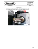
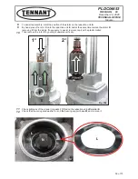
Reassemble the stator
D
and then the rotor
C
on the reduction unit
E
, repeating the dismantling operations
in reverse, as described from point 9 to point 12 in the previous paragraph.
13
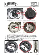
Observe the mark made on the stator
D
and the reduction unit E before dismantling.
14
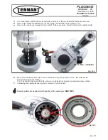
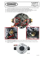
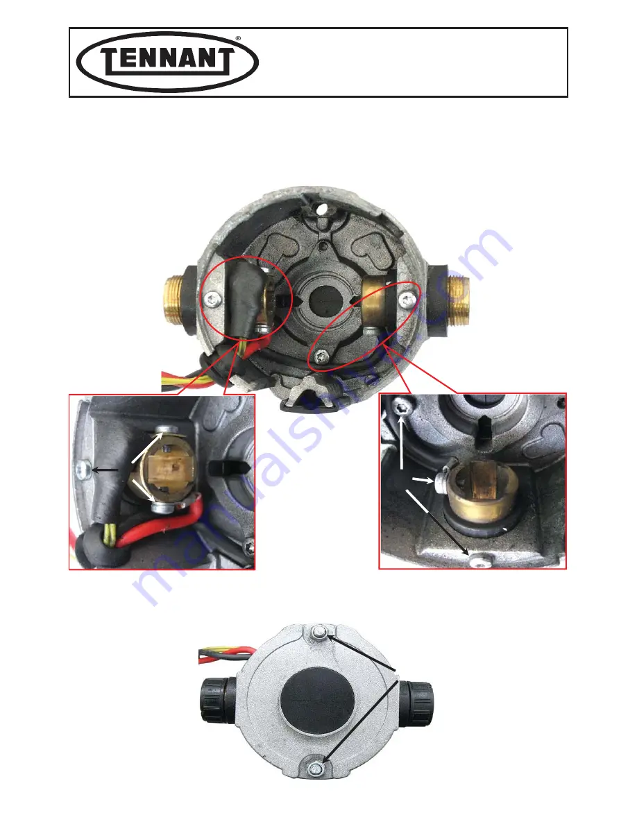
Make sure the cables that power the carbon brushes B are intact and the corresponding screws
B1
that fasten them to the carbon brush supports and the latter to the cap
A
are tight.
15
Check operation of the thermal cutout
B2
, and make sure it is secure.
15
If everything is OK, complete assembly of the motor, fitting the cap
A
, otherwise resolve the problems
and then complete assembly.
16
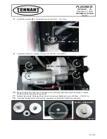
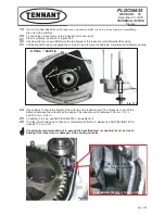
Tighten the two nuts
A1
that fasten the cap
A
to the motor-reduction unit. Tighten to a maximum torque
of 5 Nm ~ 44 lbf in.
Fig. 115
A
B1
B2
B1
B2
B1
B1
A1
5 Nm ~ 44 lbf in
Fig. 116
54 of 73

