ELECTRICAL
4-29
6200E 330415 (5--99)
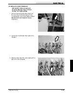
4. Note the orientation of the existing
directional control unit. Remove it from the
pedal assembly.
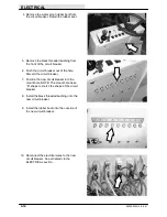
5. Install the new directional control unit onto
the pedal assembly in the same orientation
as the old one. Reinstall the two screws and
hand tighten tight.
6. With the directional pedal in the neutral
position, reinstall the accelerator lever onto
the shaft of the potentiometer. Hand tighten
the hex screw and nut.
7. Check the length of the threaded rod/ball
joint assembly. Measure the distance
between the ball joint centers. The
dimension should be approximately 4
inches. If an adjustment needs to be made,
loosen the upper jam nut and turn the rod.
Re--tighten the jam nut.
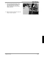
8. Reinstall the directional pedal assembly into
the machine. See TO INSTALL
DIRECTIONAL PEDAL ASSEMBLY
instructions in this section.
9. Operate the machine. Check the new
directional control unit for proper operation.
Summary of Contents for 6200E
Page 1: ...330415 Rev 01 12 01 Service Manual 6200E...
Page 4: ...GENERAL INFORMATION 6200E 330415 6 99 1 2...
Page 18: ...GENERAL INFORMATION 1 16 6200E 330415 12 01...
Page 20: ...CHASSIS 2 2 6200E 330415 6 99...
Page 74: ...SWEEPING 3 2 6200E 330415 6 99...
Page 122: ...ELECTRICAL 4 2 6200E 330415 6 99...
Page 171: ...ELECTRICAL 4 51 6200E 330415 12 01...
Page 172: ...ELECTRICAL 4 52 6200E 330415 12 01 ELECTRICAL SCHEMATIC 000000 002089 1 2 3 4 352868 E...
Page 173: ...ELECTRICAL 4 53 6200E 330415 12 01 ELECTRICAL SCHEMATIC 000000 002089 1 2 3 4 352868 E...
Page 174: ...ELECTRICAL 4 54 6200E 330415 12 01 ELECTRICAL SCHEMATIC 002090 1 2 3 4 352868 E...
Page 175: ...ELECTRICAL 4 55 6200E 330415 12 01 ELECTRICAL SCHEMATIC 002090 1 2 3 4 352868 E...
Page 176: ...ELECTRICAL 4 56 6200E 330415 12 01 MAIN WIRE HARNESS GROUP...
Page 177: ...ELECTRICAL 4 57 6200E 330415 12 01 MAIN WIRE HARNESS GROUP 352868 E...
Page 178: ...ELECTRICAL 4 58 6200E 330415 12 01 MAIN WIRE HARNESS GROUP 352868 E...
Page 179: ...ELECTRICAL 4 59 6200E 330415 12 01 MAIN WIRE HARNESS GROUP 352868 E...
Page 180: ...ELECTRICAL 4 60 6200E 330415 12 01 MAIN WIRE HARNESS GROUP 352868 E...
Page 181: ...ELECTRICAL 4 61 6200E 330415 12 01 HOPPER WIRE HARNESS GROUP 352868 E...
Page 182: ...ELECTRICAL 4 62 6200E 330415 12 01...
Page 185: ...ELECTRICAL 4 65 6200E 330415 6 99 Fig 1...
Page 186: ...ELECTRICAL 4 66 6200E 330415 6 99 Fig 2...
Page 187: ...ELECTRICAL 4 67 6200E 330415 6 99 Fig 3...
Page 190: ...ELECTRICAL 4 70 6200E 330415 6 99 Fig 4...
Page 191: ...ELECTRICAL 4 71 6200E 330415 6 99 EITHER THE FOR WARD OR REVERSE CIR CUIT BUT NOT BOTH Fig 5...
Page 192: ...ELECTRICAL 4 72 6200E 330415 6 99 Fig 6...
Page 196: ...ELECTRICAL 4 76 6200E 330415 6 99 Fig 8...
Page 197: ...ELECTRICAL 4 77 6200E 330415 6 99 Fig 9...
Page 199: ...ELECTRICAL 4 79 6200E 330415 6 99 Fig 10...
Page 200: ...ELECTRICAL 4 80 6200E 330415 6 99 Fig 11...
Page 202: ...ELECTRICAL 4 82 6200E 330415 6 99 Fig 12...
Page 203: ...ELECTRICAL 4 83 6200E 330415 6 99 Fig 13...
Page 204: ...ELECTRICAL 4 84 6200E 330415 6 99...
Page 206: ...HYDRAULICS 5 2 6200E 330415 6 99...
Page 217: ...HYDRAULICS 5 13 6200E 330415 6 99 HYDRAULIC SCHEMATIC...
Page 218: ...HYDRAULICS 5 14 6200E 330415 12 01 HYDRAULIC HOSE GROUP...


