SWEEPING
3--57
6100 G/LP 330235 (9--00)
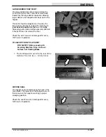
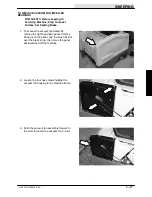
LARGE DEBRIS TRAP SKIRT
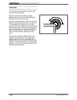
The large debris trap skirt is located along the
front of the main brush. This skirt is raised and
lowered by the large debris trap pedal, allowing
larger debris to be trapped and swept up into the
hopper.
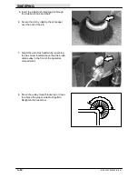
This skirt should be adjusted so it touches the
floor and is curled back, toward the main brush
(curl back should be 3/4 inch =/-- 1/4 inch).
Sweeping performance will be adversely affected
if this skirt does not contact the floor.
Check the skirt for wear or damage after every
100 hours of operation.
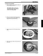
TO ADJUST FRONT FLAP SKIRT
FOR SAFETY: Before Leaving Or
Servicing Machine; Stop On Level
Surface, Set Parking Brake.
1. The front flap skirt must roll to the rear of the
machine .75 in (3/4 in) +/-- .125 in (1/8 in)
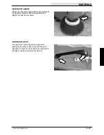
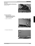
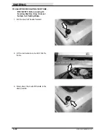
HOPPER SEAL
The hopper seal is located along the back of the
main brush. The lower lip of the hopper rests on
this seal when the hopper is setting in proper
sweeping position.
Check the seal for wear or damage after every
100 hours of operation.
Summary of Contents for 6100 G/LP
Page 1: ...330235 Rev 02 9 01 Service Manual 6100 G LP ...
Page 4: ...GENERAL INFORMATION 1 2 6100 G LP 330235 9 01 ...
Page 18: ...CHASSIS 2 2 6100 G LP 330235 9 00 ...
Page 27: ...CHASSIS 2 11 6100 G LP 330235 9 00 7 Remove the hub assembly from the tire assembly ...
Page 72: ...CHASSIS 2 56 6100 G LP 330235 9 00 ...
Page 74: ...SWEEPING 3 2 6100 G LP 330235 9 00 ...
Page 152: ...ELECTRICAL 4 2 6100 G LP 330235 9 00 ...
Page 175: ...ELECTRICAL 4 25 6100 G LP 330235 9 01 ...
Page 176: ...ELECTRICAL 4 26 6100 G LP 330235 9 01 ELECTRICAL SCHEMATIC GAS 1 2 3 4 ...
Page 177: ...ELECTRICAL 4 27 6100 G LP 330235 9 01 ELECTRICAL SCHEMATIC GAS 1 2 3 4 ...
Page 178: ...ELECTRICAL 4 28 6100 G LP 330235 9 01 ELECTRICAL SCHEMATIC LP 1 2 3 4 ...
Page 179: ...ELECTRICAL 4 29 6100 G LP 330235 9 01 ELECTRICAL SCHEMATIC LP 1 2 3 4 ...
Page 180: ...ELECTRICAL 4 30 6100 G LP 330235 9 01 WIRE DIAGRAM GAS LP ...
Page 181: ...ELECTRICAL 4 31 6100 G LP 330235 9 01 WIRE DIAGRAM GAS LP ...
Page 182: ...ELECTRICAL 4 32 6100 G LP 330235 9 01 ...
Page 190: ...ELECTRICAL 4 40 6100 G LP 330235 9 00 ...
Page 192: ...HYDRAULICS 5 2 6100 G LP 330235 9 00 ...
Page 198: ...HYDRAULICS 5 8 6100 G LP 330235 9 00 9 Disengage the prop rod and close the seat support ...
Page 205: ...HYDRAULICS 5 15 6100 G LP 330235 9 00 10 Disengage the seat rod and close the seat assembly ...
Page 217: ...HYDRAULICS 5 27 6100 G LP 330235 9 00 HYDRAULIC SCHEMATIC ...
Page 218: ...HYDRAULICS 5 28 6100 G LP 330235 9 00 OUT IN B A B A HYDRAULIC HOSE DIAGRAM ...
Page 220: ...HYDRAULICS 5 30 6100 G LP 330235 9 00 ...
Page 221: ......
Page 222: ......
Page 223: ......
Page 224: ......
Page 225: ......
Page 226: ......
Page 227: ......
Page 228: ......
Page 229: ......
Page 230: ......
Page 231: ......
Page 232: ......
Page 233: ......
Page 234: ......
Page 235: ......
Page 236: ......
Page 237: ......
Page 238: ......
Page 239: ......
Page 240: ......
Page 241: ......
Page 242: ......
Page 243: ......
Page 244: ......
Page 245: ......
Page 246: ......
Page 247: ......
Page 248: ......
Page 249: ......
Page 250: ......
Page 252: ...ENGINE GAS LP 6 2 6100 G LP 330235 9 00 ...

