SWEEPING
3--32
6100 G/LP 330235 (9--00)
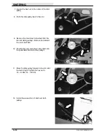
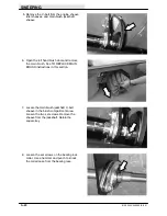
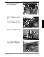
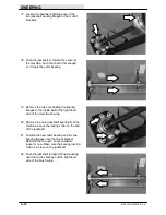
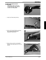
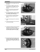
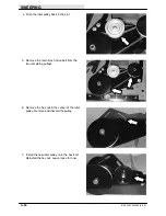
17. Loosen the hardware holding each of the
two jackshaft bearing flanges to the mount
brackets.
18. Push the jackshaft in, toward the center of
the machine. Push the shaft in far enough
so it clears the outer bearing.
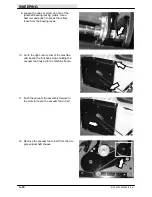
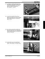
19. Remove the two nuts holding the bearing
flanges to the inside wall of the right hand
side of the main brush wrap.
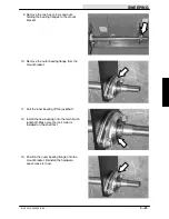
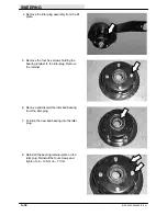
20. Remove the outer jackshaft bearing from the
machine. Leave the locking collar on the end
of the jackshaft.
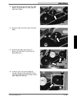
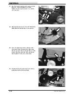
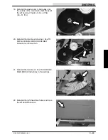
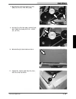
21. Position the new outer bearing and the two
bearing flanges onto the mount bracket.
Reinstall the two nuts. Leave hardware
loose for now. Make sure the bearing locking
collar is in place on the jackshaft.
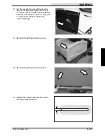
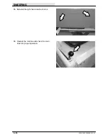
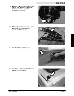
22. Push the jackshaft through the new bearing
until the end is showing out the right hand
side of the brush wrap.
Summary of Contents for 6100 G/LP
Page 1: ...330235 Rev 02 9 01 Service Manual 6100 G LP ...
Page 4: ...GENERAL INFORMATION 1 2 6100 G LP 330235 9 01 ...
Page 18: ...CHASSIS 2 2 6100 G LP 330235 9 00 ...
Page 27: ...CHASSIS 2 11 6100 G LP 330235 9 00 7 Remove the hub assembly from the tire assembly ...
Page 72: ...CHASSIS 2 56 6100 G LP 330235 9 00 ...
Page 74: ...SWEEPING 3 2 6100 G LP 330235 9 00 ...
Page 152: ...ELECTRICAL 4 2 6100 G LP 330235 9 00 ...
Page 175: ...ELECTRICAL 4 25 6100 G LP 330235 9 01 ...
Page 176: ...ELECTRICAL 4 26 6100 G LP 330235 9 01 ELECTRICAL SCHEMATIC GAS 1 2 3 4 ...
Page 177: ...ELECTRICAL 4 27 6100 G LP 330235 9 01 ELECTRICAL SCHEMATIC GAS 1 2 3 4 ...
Page 178: ...ELECTRICAL 4 28 6100 G LP 330235 9 01 ELECTRICAL SCHEMATIC LP 1 2 3 4 ...
Page 179: ...ELECTRICAL 4 29 6100 G LP 330235 9 01 ELECTRICAL SCHEMATIC LP 1 2 3 4 ...
Page 180: ...ELECTRICAL 4 30 6100 G LP 330235 9 01 WIRE DIAGRAM GAS LP ...
Page 181: ...ELECTRICAL 4 31 6100 G LP 330235 9 01 WIRE DIAGRAM GAS LP ...
Page 182: ...ELECTRICAL 4 32 6100 G LP 330235 9 01 ...
Page 190: ...ELECTRICAL 4 40 6100 G LP 330235 9 00 ...
Page 192: ...HYDRAULICS 5 2 6100 G LP 330235 9 00 ...
Page 198: ...HYDRAULICS 5 8 6100 G LP 330235 9 00 9 Disengage the prop rod and close the seat support ...
Page 205: ...HYDRAULICS 5 15 6100 G LP 330235 9 00 10 Disengage the seat rod and close the seat assembly ...
Page 217: ...HYDRAULICS 5 27 6100 G LP 330235 9 00 HYDRAULIC SCHEMATIC ...
Page 218: ...HYDRAULICS 5 28 6100 G LP 330235 9 00 OUT IN B A B A HYDRAULIC HOSE DIAGRAM ...
Page 220: ...HYDRAULICS 5 30 6100 G LP 330235 9 00 ...
Page 221: ......
Page 222: ......
Page 223: ......
Page 224: ......
Page 225: ......
Page 226: ......
Page 227: ......
Page 228: ......
Page 229: ......
Page 230: ......
Page 231: ......
Page 232: ......
Page 233: ......
Page 234: ......
Page 235: ......
Page 236: ......
Page 237: ......
Page 238: ......
Page 239: ......
Page 240: ......
Page 241: ......
Page 242: ......
Page 243: ......
Page 244: ......
Page 245: ......
Page 246: ......
Page 247: ......
Page 248: ......
Page 249: ......
Page 250: ......
Page 252: ...ENGINE GAS LP 6 2 6100 G LP 330235 9 00 ...

