Warning Symbol
This symbol calls attention to an operating procedure, prac-
tice, or the like which, if not correctly performed or adhered
to, could result in personal injury or damage to or destruc-
tion of part or all of the product and system. Do not proceed
beyond a warning symbol until the indicated conditions are
fully understood and met.
Using the Manual
• Installers . . . . . . . . . . . . . . . . . . . . . Read Chapter 1, 2
• System Designer . . . . . . . . . . . . . . . Read All Chapters
• Expert User . . . . . . . . . . . . . . . . . . . Read Page 11
Information in this user's manual is subject to change with-
out notice.
Copyright © 2008, Tempco Electric Heater Corporation, all
rights reserved. No part of this publication may be repro-
duced, transmitted, transcribed or stored in a retrieval sys-
tem, or translated into any language in any form by any
means without the written permission of Tempco Electric
Heater Corporation.
Contents
Page No.
Chapter 1 Overview
1-1 General . . . . . . . . . . . . . . . . . . . . . . . . . . . . . . . . . 1
1-2 Ordering Code . . . . . . . . . . . . . . . . . . . . . . . . . . . 1
1-3 Programming Port . . . . . . . . . . . . . . . . . . . . . . . . 2
1-4 Keys and Displays . . . . . . . . . . . . . . . . . . . . . . . . 2
1-5 Menu Overview . . . . . . . . . . . . . . . . . . . . . . . . . . 6
1-6 Menu Overview . . . . . . . . . . . . . . . . . . . . . . . . . . 7
1-7 Parameter Descriptions. . . . . . . . . . . . . . . . . . . . . 8
Chapter 2 Installation
2-1 Unpacking . . . . . . . . . . . . . . . . . . . . . . . . . . . . . . 11
2-2 Mounting . . . . . . . . . . . . . . . . . . . . . . . . . . . . . . . 11
2-3 Wiring Precautions . . . . . . . . . . . . . . . . . . . . . . . 11
2-4 Power Wiring . . . . . . . . . . . . . . . . . . . . . . . . . . . 12
2-5 Sensor Installation Guidelines . . . . . . . . . . . . . . 12
2-6 Thermocouple Input Wiring . . . . . . . . . . . . . . . . 12
2-7 RTD Input Wiring . . . . . . . . . . . . . . . . . . . . . . . . 13
2-8 Linear DC Input Wiring . . . . . . . . . . . . . . . . . . . 13
2-9 Event Input Wiring . . . . . . . . . . . . . . . . . . . . . . . 14
2-10 Output 1 Wiring . . . . . . . . . . . . . . . . . . . . . . . . 14
2-11 Output 2 Wiring . . . . . . . . . . . . . . . . . . . . . . . . 15
2-12 RS-485 . . . . . . . . . . . . . . . . . . . . . . . . . . . . . . . 16
2-13 RS-232 . . . . . . . . . . . . . . . . . . . . . . . . . . . . . . . 16
2-14 Retransmission . . . . . . . . . . . . . . . . . . . . . . . . . 16
Chapter 3 Programming
3-1 Process Input . . . . . . . . . . . . . . . . . . . . . . . . . . . 17
3-2 Limit Control . . . . . . . . . . . . . . . . . . . . . . . . . . . 17
3-3 Set Point Range . . . . . . . . . . . . . . . . . . . . . . . . . 18
3-4 PV Shift . . . . . . . . . . . . . . . . . . . . . . . . . . . . . . . . 13
3-5 Digital Filter . . . . . . . . . . . . . . . . . . . . . . . . . . . . 18
3-6 Process Alarms . . . . . . . . . . . . . . . . . . . . . . . . . . 19
3-7 Data communication . . . . . . . . . . . . . . . . . . . . . . 20
3-8 Process Variable (PV) Retransmission . . . . . . . . 20
3-9 Signal Conditioner DC Power Supply . . . . . . . . 21
3-10 Remote Reset . . . . . . . . . . . . . . . . . . . . . . . . . . 21
3-11 Remote Lock . . . . . . . . . . . . . . . . . . . . . . . . . . . 22
3-12 Limit Annunciator . . . . . . . . . . . . . . . . . . . . . . 22
3-13 Reference Data . . . . . . . . . . . . . . . . . . . . . . . . . 22
Chapter 4 Application
. . . . . . . . . . . . . . . . . . . . 23
Chapter 5 Calibration
. . . . . . . . . . . . . . . . . . . . . . 25
Chapter 6 Specifications
. . . . . . . . . . . . . . . . . . . 27
Chapter 7 Modbus Communications
7-1 Functions Supported . . . . . . . . . . . . . . . . . . . . . . 29
7-2 Exception Responses . . . . . . . . . . . . . . . . . . . . . 30
7-3 Parameter Table . . . . . . . . . . . . . . . . . . . . . . . . . 30
7-4 Data Conversion . . . . . . . . . . . . . . . . . . . . . . . . . 32
7-5 Communication Examples. . . . . . . . . . . . . . . . . . 33
Appendix
A-1 Error Codes . . . . . . . . . . . . . . . . . . . . . . . . . . . . 34
A-2 Warranty . . . . . . . . . . . . . . . . . . . . . . . . . . . . . . . 35
Figures & Tables
Page No.
Figure 1.1 Access Overview . . . . . . . . . . . . . . . . . . . . 2
Figure 1.2 Front Panel Deplay . . . . . . . . . . . . . . . . . . 3
Figure 1.3 Power Up Sequence . . . . . . . . . . . . . . . . . 4
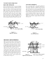
Figure 1.4 High Limit Operation . . . . . . . . . . . . . . . . 7
Figure 1.5 Low Limit Operation. . . . . . . . . . . . . . . . . 7
Figure 1.6 High/Low Limit Operation . . . . . . . . . . . . 7
Figure 2.1 Mounting Diagram . . . . . . . . . . . . . . . . . 11
Figure 2.2 Lead Termination . . . . . . . . . . . . . . . . . . . 11
Figure 2.3 Rear Terminal Connection Diagram . . . . 11
Figure 2.4 Power Supply Connections . . . . . . . . . . . 12
Figure 2.5 Thermocouple Input Wiring . . . . . . . . . . 12
Figure 2.6 RTD Input Wiring. . . . . . . . . . . . . . . . . . . 13
Figure 2.7 Linear Voltage Input Wiring . . . . . . . . . . 13
Figure 2.8 Linear Current Input Wiring . . . . . . . . . . 13
Figure 2.9 Event Input Wiring . . . . . . . . . . . . . . . . . . 14
Figure 2.10 Output 1 Wiring . . . . . . . . . . . . . . . . . . . 14
Figure 2.11 Output 2 Wiring . . . . . . . . . . . . . . . . . . . 15
Figure 2.12 RS-485 Wiring . . . . . . . . . . . . . . . . . . . . 16
Figure 2.13 RS-232 Wiring . . . . . . . . . . . . . . . . . . . . 16
Figure 2.14 Configuration of RS-232 Cable . . . . . . 16
Figure 2.15 Retransmission Wiring . . . . . . . . . . . . . 16
Figure 3.1 Conversion Curve for Linear Type
Process Value . . . . . . . . . . . . . . . . . . . . . . 17
Figure 3.2 Filter Characteristics. . . . . . . . . . . . . . . . . 18
Figure 3.3 Normal Process Alarm . . . . . . . . . . . . . . . 19
Figure 3.4 Latching Process Alarm . . . . . . . . . . . . . . 19
Figure 3.5 DC Power Supply Application . . . . . . . . . 20
Figure 3.6 Remote Reset Application . . . . . . . . . . . . 22
Figure 3.7 Remote Lock Application. . . . . . . . . . . . . 22
Figure 4.1 Over Temperature Protection with
Remote Reset . . . . . . . . . . . . . . . . . . . . . . 23
Figure 5.1 Flow Chart for Manual Calibration . . . . . 25
Figure 5.2 Cold Junction Calibration Setup . . . . . . . 25
Figure 5.3 RTD Calibration . . . . . . . . . . . . . . . . . . . . 26
Table 1.1 DIP Switch Configuration . . . . . . . . . . . . . 2
Table 1.2 Display Form of Characters . . . . . . . . . . . . 3
Table 6.1 Input Characteristics . . . . . . . . . . . . . . . . . 27
Table A.1 Error Codes and Corrective Actions . . . . . 34
Summary of Contents for TEC-410
Page 26: ...24 ...


