background image

7

H

S

P1

ON
OFF

OUT1 Relay

A, B ,C = Re

s

et i

s

 applied

O1.HY = Output1 hy

s

tere

s

i

s

PV

A

B

C

H

S

P1 – O1.HY

Figure 1.4

High Limit Operation

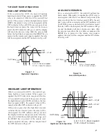
HIGH LIMIT OPERATION

If Hi. is selected for OUT1, the unit will perform
high limit control. When power is applied the OUT1
relay is de-energized. After the 6.5 second self-test
period, if the process is below the high limit set point
(HSP1) the output 1 relay will be energized and the
OP1 indicator will go off.If the process goes above
the high limit set point, the relay will be de-ener-
gized, the OP1 indicator will go on, and the display
will show the process value. After the process falls
below the high limit set point and the RESET key is
pressed or the remote reset input is applied, the relay
will be energized and the OP1 indicator will go off.

1–6 Limit Control Operation

LOW LIMIT OPERATION

If Lo. is selected for OUT1, the unit will perform low
limit control. When power is applied the OUT1 relay is
de-energized. After the 6.5 second self-test period, if the
process is above the low limit set point (LSP1) the out-
put 1 relay will be energized and the OP1 indicator will
go off.If the process goes below the low limit set point,
the relay will be de-energized, the OP1 indicator will go
on, and the display will show the process value. After
the process rises above the low limit set point and the
RESET key is pressed or the remote reset input is
applied, the relay will be energized and the OP1 indica-
tor will go off.

L

S

P1

ON
OFF

OUT1 Relay

A, B ,C = Re

s

et i

s

 applied

O1.HY = Output1 hy

s

tere

s

i

s

A

B

C

L

S

P1 + O1.HY

Figure 1.5

Low Limit Operation

HIGH/LOW LIMIT OPERATION

If Hi.Lo is selected for OUT1, the unit will per-
form high/low limit control. When power is
applied, the OUT1 relay is de-energized. After the
6.5 second self-test period, if the process is below
the high limit set point (HSP1) and above the low
limit set point (LSP1), the output 1 relay will be
energized and the OP1 indicator will go off.

If the process goes above the high limit set point
or below the low limit set point, the relay will be
de-energized, the OP1 indicator will go on, and
the display will show the process value. After the
process is within the normal operation range, and
the RESET key is pressed or the remote reset
input is applied, the relay will be energized and
the OP1 indicator will go off.

L

S

P1 + O1.HY

H

S

P1

L

S

P1

H

S

P1 – O1.HY 

ON
OFF

OUT1 Relay

A, B, C, D, E, F =Re

s

et i

s

 applied

O1.HY= Output1 hy

s

tere

s

i

s

A

BC

D

E F

Figure 1.6

High/Low Limit Operation

Summary of Contents for TEC-410

Page 1: ...ssor Based Limit Controller Manual TEC 410 Revision 8 2008 TEMPCO Electric Heater Corporation 607 N Central Avenue Wood Dale IL 60191 1452 USA Tel 630 350 2252 Toll Free 800 323 6859 Fax 630 350 0232 E mail info tempco com Web www tempco com Agency Approvals ...

Page 2: ...ioner DC Power Supply 21 3 10 Remote Reset 21 3 11 Remote Lock 22 3 12 Limit Annunciator 22 3 13 Reference Data 22 Chapter 4 Application 23 Chapter 5 Calibration 25 Chapter 6 Specifications 27 Chapter 7 Modbus Communications 7 1 Functions Supported 29 7 2 Exception Responses 30 7 3 Parameter Table 30 7 4 Data Conversion 32 7 5 Communication Examples 33 Appendix A 1 Error Codes 34 A 2 Warranty 35 F...

Page 3: ...r lower than the low limit set point The unit is powered by 11 26 or 90 250VDC VAC supply voltage incorporates a 3 amp form C relay for limit control a universal input which is fully programmable for PT100 thermocouple types J K T E B R S N L and 0 60mV and an option port is available for one of the following functions RS 232 RS 485 communication interface and Retransmission Alternative output opt...

Page 4: ... will occur If the unit subsequently goes into a state where reset is required again the RESET key or remote reset contacts must be released opened and pressed closed again UNLOCK KEY 4 seconds Press the RESET key for 4 seconds to enable up down key function and the lock indicator will be extinguished However this function is disabled when the EI input pins are closed and remote lock is selected f...

Page 5: ...et point value parameter value etc Lock Status Indicator The reference data are reset as long as the reset key is pressed for 4 seconds See section 3 13 TEMPCO Out1 Out2 Figure 1 2 Front Panel Display How to display a 5 digit number For a number with a decimal point the display will be shifted one digit to the right 199 99 will be displayed as 199 9 4553 6 will be displayed as 4553 For a number wi...

Page 6: ...OR BREAK DISPLAY If a break is detected in the sensor circuit the display will show SENB A D FAILURE DISPLAY If failure is detected in the A D converter circuit the display will show AD ER Lock R LIMIT CONTROL LIMIT CONTROL TEC 410 TEMPCO Lock R LIMIT CONTROL LIMIT CONTROL TEC 410 TEMPCO All segments of display and indicators are left off for 0 5 second All segments of display and indicators are l...

Page 7: ...onds Display the hours used for 1 5 seconds The example shows that the unit has been used for 23456 7 hours since production Lock R LIMIT CONTROL LIMIT CONTROL TEC 410 TEMPCO Lock R LIMIT CONTROL LIMIT CONTROL TEC 410 TEMPCO Lock R LIMIT CONTROL LIMIT CONTROL TEC 410 TEMPCO Verify that all electrical connections have been made properly before apply ing power to the unit During power up a self test...

Page 8: ...Alarm hysteresis value Alarm failure transfer Event input function Normal display format Press for 4 sec PV HI PV LO Max historical PV Min historical PV T ABN Abnormal time PV Value SP1 or SAFE HSP1 Value __ __ __ __ LSP1 Value __ __ __ __ SP2 Value __ __ __ __ High limit setpoint 1 value Low limit setpoint 1 value Set point 2 value Setup Mode Press for 2 sec Calibration Mode 1 5 Menu Overview Not...

Page 9: ...goes below the low limit set point the relay will be de energized the OP1 indicator will go on and the display will show the process value After the process rises above the low limit set point and the RESET key is pressed or the remote reset input is applied the relay will be energized and the OP1 indica tor will go off LSP1 ON OFF OUT1 Relay A B C Reset is applied O1 HY Output1 hysteresis A B C L...

Page 10: ... 1 decimal digit 2 2 DP 2 decimal digits 3 3 DP 3 decimal digits 0 J TC J type thermocouple 1 K TC K type thermocouple 2 T TC T type thermocouple 3 E TC E type thermocouple 4 B TC B type thermocouple 5 R TC R type thermocouple 6 S TC S type thermocouple 7 N TC N type thermocouple 8 L TC L type thermocouple 9 C TC C type thermocouple 10 P TC P type thermocouple 11 PTDN PT 100 ohms DIN curve 12 PTJS...

Page 11: ...D 8 bit odd parity 2 NONE 8 bit none parity Analog Retransmission Output Function 0 PV Process Value 1 HSP1 High Limit Set point 1 2 LSP1 Low Limit Set point 1 BAUD BAUD PARI PARI AOFN AOFN Low 19999 High 45536 0 0 C 32 0 F Analog Output Low Scale Value AOLO AOLO Low 19999 High 45536 100 0 C 212 0 F Analog Output High Scale Value AOHI AOHI Output 1 Hysteresis Value Low 0 1 High 10 0 C 18 0 F 1 O1 ...

Page 12: ...ow 0 1 High 10 C 18 F 0 1 AL HY AL HY Alarm failure transfer 0 OFF Alarm Output goes off as unit fails 1 ON Alarm Output goes on as unit fails 1 AL FT AL FT Event input function 0 EIFN EIFN DISP DISP Normal display format 0 SAFE Display SAFE 1 HSP1 Display the value of HSP1 2 LSP1 Display the value of LSP1 0 Parameter Notation Default Value Parameter Description Refer to Page Range 0 NONE No event...

Page 13: ...tout Reinstall the mounting clamp and screws Gently tighten the screws until the front panel fits snugly in the cutout Chapter 2 Installation 53 mm 2 1 8 Panel Panel Cutout 92 mm 3 5 8 92 mm 3 5 8 Figure 2 1 Mounting Diagram 2 3 Wiring Precautions Before wiring verify the correct model number and options on the label Switch off the power while checking Care must be taken to ensure that the maximum...

Page 14: ...lel will provide an average temperature readout and produce better results in most air heated processes Proper sensor type is also a very important factor in obtain ing precise measurements The sensor must have the correct temperature range to meet the process requirements In spe cial processes the sensor might have requirements such as leak proof anti vibration antiseptic etc Standard sensor limi...

Page 15: ...e RTD will produce 1 C temperature error Figure 2 6 RTD Input Wiring 1 1 2 2 3 3 4 4 ON ON Dip Switch 1 2 3 4 5 6 7 8 9 10 11 12 13 14 15 16 17 18 19 20 RTD RTD 1 2 3 4 5 6 7 8 9 10 11 12 13 14 15 16 17 18 19 20 Three Wire RTD Two Wire RTD 1 2 3 4 O N 0 20mA or 4 20mA 1 2 3 4 5 6 7 8 9 10 11 12 13 14 15 16 17 18 19 20 Dip Switch Figure 2 8 Linear Current Wiring Figure 2 7 Linear Voltage Wiring 1 2...

Page 16: ...ontroller Output No Fuse Breaker Contactor Three Phase Heater Power 1 2 3 4 5 6 7 8 9 10 11 12 13 14 15 16 17 18 19 20 1 2 3 4 5 6 7 8 9 10 11 12 13 14 15 16 17 18 19 20 Relay or Triac Output Direct Drive Relay or Triac Output to Direct Contactor Three Phase Delta Heater Load 120V 240V Mains Supply To Controller Output SSR 1 2 3 4 5 6 7 8 9 10 11 12 13 14 15 16 17 18 19 20 120V 240V Mains Supply 3...

Page 17: ...ge to Drive SSR 5V 33 33 0V 7 8 Internal Circuit 120V 240V Mains Supply Three Phase Heater Power No Fuse Breaker Three Phase Delta Heater Load Contactor Relay or Triac Output to Drive Contactor 1 2 3 4 5 6 7 8 9 10 11 12 13 14 15 16 17 18 19 20 Relay or Triac Output Direct Drive 120V 240V Mains Supply Max 2A Resistive Load 2 11 Output 2 Wiring Figure 2 11 Output 2 Wiring ...

Page 18: ...EC99014 Figure 2 13 RS 232 Wiring 1 2 3 4 5 6 7 8 9 L41 TX1 TX1 RD 13 14 10 TX2 TX2 TD COM COM GND 1 DCD 2 RD 3 TD 4 DTR 5 GND 6 DSR 7 RTS 8 CTS 9 RI PC Female DB 9 To DTE PC RS 232 Port Figure 2 13 RS 232 Wiring Figure 2 14 Configuration of RS 232 Wiring 2 13 RS 232 Load Load Load The total effective resistance of serial loads can t exceed 500 ohms 1 2 3 4 5 6 7 8 9 10 11 12 13 14 15 16 17 18 19 ...

Page 19: ...ss unit RESO Selects the location of the decimal point Resolution for most not all process related parameters IN LO Selects the low scale value for the linear type input Hidden if T C or RTD type is selected for INPT IN HI Selects the high scale value for the linear type i n p u t Hidden if T C or RTD type is selected for INPT How to use IN LO and IN HI If 4 20mA is selected for INPT SL specifies ...

Page 20: ...just either positive or negative will be added to the actual value The SHIF function will alter the process variable PV only SHIF PV shift offset value PV Time FILT 0 1sec FILT 1 FILT 30 1sec 3 5 Digital Filter In certain applications the process value is too unstable to be read To improve this a programmable low pass filter is incorporated in the TEC 410 This is a first order filter with the time...

Page 21: ... AL MD that can be selected They are Normal Alarm NORM and Latching Alarm LATCH Normal Alarm AL MD NORM When the normal alarm is selected the alarm output is de energized in the non alarm condition and energized in an alarm condition Latching Alarm AL MD LTCH If the latching alarm is selected once the alarm output is energized it will remain unchanged even if the alarm condition has been cleared u...

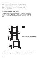
Page 22: ... 4 5 6 7 8 9 10 11 12 13 14 15 16 17 18 19 20 1 2 3 4 5 6 7 8 9 10 11 12 13 14 15 16 17 18 19 20 1 2 3 4 5 6 7 8 9 10 11 12 13 14 15 16 17 18 19 20 3 8 Signal Conditioner DC Power Supply Three types of isolated DC power supplies are available to supply an external transmitter or sensor These are 20V rated at 25mA 12V rated at 40mA and 5V rated at 80mA DC voltage is delivered to the output 2 termin...

Page 23: ...t error over a 1km distance while RS 232 is not recommended for a distance of over 60 feet 20 meters Using a PC for data communication is the most economi cal method The signal is transmitted and received through the PC communication port generally RS 232 Since a standard PC can t support an RS 485 port a network adapter such as TEC99001 has to be used to convert RS 485 to RS 232 for a PC if RS 48...

Page 24: ...ged If the switch is opened the lock indicator is extinguished and the up down key is enabled 3 13 Reference Data There are three reference data points stored by the control and accessed in the setup menu The reference data are read only data The maximum historical PV displayed by PV HI which shows the maximum process value since the last UNLOCK operation The minimum historical PV displayed by PV ...

Page 25: ...EC 410 limit control is used to protect the process from being overheated The wiring diagram is shown below 1 2 3 4 5 6 7 8 9 10 1 Remote Reset EI EI Temperature Control TEC 9100 L N _ Heater Mechanical Contactor 1 2 3 4 5 6 7 8 9 10 11 12 13 14 15 16 17 18 19 20 Figure 4 1 Over Temperature Protection with Remote Reset Chapter 4 Application ...

Page 26: ...24 ...

Page 27: ...to D converter Send a span signal to terminals 4 and 5 with the correct polarity The span signal is 60mV for thermocouple input 1V for 0 1V input 10V for 0 10V input and 20mA for 0 20mA input Press for at least 4 seconds The display will blink for a moment If the display didn t blink then calibration failed Step 3 Calibrate the offset of the cold junction compensa tion Set up the equipment accordi...

Page 28: ...alibration procedures for a linear volt age or a linear current input 1 Change resistor R62 on the control board with the recommended values specified in Table 5 1 Low temperature coefficient resistors with 1 50ppm should be used for R62 Adjust the DIP switch according to Table 1 1 1 2 3 4 5 6 7 8 9 10 100 ohms Input Function R62 T C RTD 0 60mV 28K 0 1 V 0 5V 1 5V 0 10 V 150K 300K 300K 2 Perform s...

Page 29: ...DIN 2ºC 0 05 0ºC to 1767 8ºC 32ºF to 3214ºF 250ºC to 1300ºC 418ºF to 2372ºF 200ºC to 900ºC 328ºF to 1652ºF 200ºC to 600ºC 328ºF to 1112ºF R S N L PT100 JIS mV mA V 210ºC to 700ºC 346ºF to 1292ºF 8mV to 70mV 3mA to 27mA 1 3V to 11 5V 0 05 0 05 70 5 650 K 1 3 K 1 3 K Characteristics 2ºC 2ºC 2ºC 200ºC to 1800ºC 2ºC 2ºC 2ºC 2ºC 0 4ºC 0 4ºC 2ºC 2 2 M 2 2 M 0ºC to 2315ºC 32ºF to 4199ºF 0ºC to 1395ºC 32º...

Page 30: ...U mode Address 1 247 Baud Rate 0 3 38 4 Kbits sec Data Bits 8 bits Parity Bit None even or odd Stop Bit 1 or 2 bits Communication Buffer 50 bytes Analog Retransmission Output Signal 4 20 mA 0 20 mA 0 5V 1 5V 0 10V Resolution 15 bits Accuracy 0 05 of span 0 0025 C Load Resistance 0 500 ohms for current output 10K ohms minimum for voltage out put Output Regulation 0 01 for full load change Output Se...

Page 31: ...ers Query from master Response from slave Slave address 0 255 Function code 16 Starting address of register Hi 0 Starting address of register Lo 0 61 128 143 No of words Hi 0 No of words Lo 1 18 Byte count 2 36 CRC16 Hi Data 1 Hi CRC16 Lo Data 1 Lo Data 2 Hi Data 2 Lo CRC16 Hi CRC16 Lo 7 1 Functions Supported Only function 03 06 and 16 are available for this series of controllers The message forma...

Page 32: ...27 Reserved 28 HSP L Lower limit of HSP1 1 1 R W 29 HSP H Upper limit of HSP1 1 1 R W 30 LSP L Lower limit of LSP1 1 1 R W 31 LSP H Upper limit of LSP1 1 1 R W 32 Reserved 30 7 2 Exception Responses If the controller receives a message which contains a corrupted character parity check error framing error etc or if the CRC16 check fails the controller ignores the message However if the controller r...

Page 33: ...calibration low coefficient 1999 9 4553 6 R W 52 ADG mV calibration high coefficient 1999 9 4553 6 R W 53 CJTL Cold junction calibration low coefficient 199 99 455 36 R W 54 CJG Cold junction calibration high coefficient 1999 9 4553 6 R W 55 REF RTD calibration low coefficient 1999 9 4553 6 R W 56 SR RTD calibration high coefficient 199 99 4553 6 R W 57 Reserved 58 DATE Manufacturing date of the p...

Page 34: ...e High 6553 5 65535 6553 5 655 35 65 535 7 4 Data Conversion The word data are regarded as unsigned positive data in the Modbus message However the actual value of the parameter may be a negative value with decimal point The high low scale values for each parameter are used for the purpose of such conversion Let M Value of Modbus message A Actual value of the parameter SL Scale low value of the pa...

Page 35: ...HI 100 0 IN LO 0 RESO 1 HI 00 4E 52 4E 00 LO 02 1F 07 1F 01 3 Preset the second group of the parameters Addr CRC16 SP2 90 0 LSP1 0 0 HSP1 100 0 Bytes HI 51 4E 52 03 01 10 LO A3 1F 07 06 00 00 Func Starting Addr No of words 4 Preset the third group of the parameters Addr O1 HY 0 1 Reserved OUT1 2 Bytes 00 00 00 00 13 11 10 01 00 00 02 26 00 00 Func Starting Addr No of words Reserved 00 00 00 00 00 ...

Page 36: ...ode Display Symbol Error Description Corrective Action Communication error bad function code 10 Correct the communication software to meet the protocol requirements Communication error register address out of range 11 Don t issue an over range register address to the slave Communication error attempt to write a read only data or a protected data 14 Don t write a read only data or a protected data ...

Page 37: ... to the first purchaser for use An extended period is available with extra cost upon request Tempco s sole responsibility under this warranty at Tempco s option is limited to replacement or repair free of charge or refund of purchase price within the warranty period specified This warranty does not apply to damage resulting from transportation alteration misuse or abuse RETURNS No product returns ...

Page 38: ...lutions Experience the Advantages of our Diverse and Innovative Products Copyright 2008 TEHC All Rights Reserved Electric Heating Elements Thermocouples and RTD Assemblies SCR Power Controls Solid State Relays Mechanical Relays Videographic Data Recorders Temperature Measurement Current Indicators Thermocouple and Power Lead Wire Wiring Accessories Serving Industry Since 1972 TEMPCO Electric Heate...

Reviews: