background image


iR1200 Modem 

www.telusmobility.com


27 


5


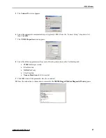
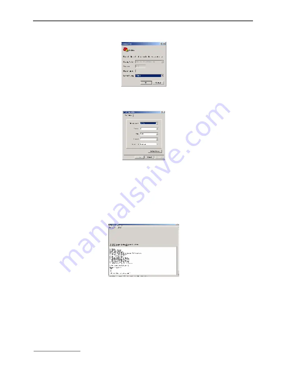
The 

Connect To

 screen appears. 


6


Select the appropriate communication port (typically COM1) from the “Connect Using:” drop down list 
then Click 

OK

7


The 

COM1 Properties

 screen appears.  


8


Select the following parameters from each of the drop-down lists on the Port Settings tab: 


19200

 for Bits per second 


8

 for Data bits 


NONE

 for Parity 


1

 for Stop bits 


None or Hardware

 for Flow control 

9


Click 

OK

 when all the parameters have been selected. 

10


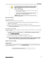
Once the connection to the modem is successful, the 

iR1200 Rugged Modem Diagnostic Menu

 appears. 


Summary of Contents for iR1200

Page 1: ...iR1200 Rugged Modem iR1200 GPS Enabled Modem INSTALLATION GUIDE ...

Page 2: ......

Page 3: ...tions 5 iR1200 Rugged Modem 6 iR1200 GPS Enabled Modem 6 Modem Specifications 6 INSTALLATION PREPARATION 8 Before You Start Installing 8 Installation Planning 8 Planning Modem Location 8 Modem Dimensions 8 Planning Antenna Location 9 Planning Cable Layout 10 Serial Cable Routing 10 Installation Tools 10 MOBILE INSTALLATION 11 Installation Steps 11 Mounting the Modem 11 Select Modem Location 11 Mou...

Page 4: ...e s 18 Route and Connect Data Cable s 18 FIXED INSTALLATION 19 Installation Steps 19 Mounting the Modem 19 Select Modem Location 19 Mount the Modem 19 Mounting the Antenna s 20 Approved Antennas 20 Select Antenna Location 20 Mount the Antenna s 20 Mount Modem Antenna 20 Mount GPS Antenna optional 21 Route and Connect Cables 21 Approved Cables 21 Route and Connect Power Cable 21 Route and Connect A...

Page 5: ...rsonal Electronic Devices 30 Pacemakers 30 Hearing Aids 30 Other Medical Devices 30 Interference with Other Electronic Devices 30 INDEX 31 IMPORTANT Please read Safety Notice on page 30 before using the modem Last Updated RFM 4200 5015 Rev 1 JULY 2004 2004 TELUS Mobility and the TELUS Mobility logo are registered trademarks of TELUS Corporation ...

Page 6: ......

Page 7: ...1200 GPS Enabled Modem 9 Figure 5 iR1200 Installation Wiring Diagram Mobile 14 Figure 6 Modem Power Wiring Diagram 14 Figure 7 Modem Ignition Wiring Diagram 15 Figure 8 Continuous Power Configuration 16 Figure 9 Wiring Diagram for Continuous Power 16 Figure 10 Docking Station Configuration 17 Figure 11 Wiring Diagram for Docking Station 17 Figure 12 iR1200 Installation Wiring Diagram Fixed 21 Figu...

Page 8: ... reasonable protection against harmful interference in a residential installation The equipment generates uses and can radiate radio frequency energy and if not installed and used in accordance with the instructions may cause harmful interference to radio communications However there is no guarantee that interference will not occur in a particular installation If this equipment does cause harmful ...

Page 9: ...r s guides an Installation Guide and Configuration Guide The Installation Guide is provided to you on the CD that can be found in the box The Configuration Guide provides detailed instructions on how to install the iDEN packet data applet and configure the modem to communication within the iDEN Network The Configuration guide can be downloaded from the Product Support page on the www elutions com ...

Page 10: ... iR1200 GPS Enabled Modem in normal mode you must have an activated data account with TELUS Mobility iDEN Packet Data Applet The iDEN Packet Data Applet must be downloaded and successfully installed on the computer laptop MDT that the modem is connected to Please refer to the Installing iDEN Packet Data Applet section of the Configuration Guide for instructions on how to download and install the d...

Page 11: ...reless modem connection used for accessing the Internet sending and receiving e mail and transferring small files over the packet data network using standard IP protocols Data is sent in packets blocks of data at high speed Circuit Switched Data A wireless modem connection for sending and receiving data faxes files etc over the circuit switched cellular channel providing a direct point to point co...

Page 12: ...a Connector Ignition Sense Bypass Connector GPS Antenna Connector 12VDC Power Connector GPS Serial Data Connector Modem Serial Data Connector Modem Antenna Connector Ignition Sense Bypass Connector Figure 3 Rear Panel of iR1200 GPS Enabled Modem Modem Specifications Transmission Modes Circuit Switched Packet Data Hayes AT Commands Rugged metal enclosure Extruded Aluminum Status monitoring LED One ...

Page 13: ...Shock per MIL STD 810E method 516 4 procedure I Dust Water Resistance Dust per MIL STD 810E method 510 3 procedure I Water per MIL STD 810E method 506 3 procedure II Master Reset Yes LED Lights Indicators 6 Single color LEDs for modem RS 232 signal status TX RX DR DSR CTS RTS per RS 232 C E Specifications GPS Receiver 8 channel NMEA 0183 protocol Antenna Connectors Mini UHF female for modem and MC...

Page 14: ...ponents See Required Components List on page 3 Planning Modem Location Factors to consider when planning for the location or placement of your iR1200 modem Easily Accessible You should allow easy access to the modem for troubleshooting purposes Easily Visible You should allow a clear view of the modem s LED indicators Proximity of the Cables The distance between connections especially that between...

Page 15: ...em Component Dimension Overall dimensions from connector to connector 7 86in 199 69mm End panel to end panel 7 09in 180 14mm Width including mounting tabs 5 04in 128 02mm Width of enclosure 4 04in 102 62mm Height of enclosure 2 20in 55 88mm Planning Antenna Location Factors to consider when planning for the location or placement of the antenna Choose a location with easy access to cable routing to...

Page 16: ...e to observe these restrictions will result in exceeding the FCC RF exposure limits Planning Cable Layout Once you have chosen the location of the modem and antenna and before installing layout the cables to determine If the cables can reach the modem and antenna If the distance between components is adequate and allows you to make adjustments to receive a better signal Please refer to the manufac...

Page 17: ...age 17 Installation Steps To install you must perform the following steps Mount Modem Mount the modem in the desired location Mount Antenna Mount the antenna using the instructions included with your selected antenna s installation guide Mount GPS Antenna GPS Enabled Modem only Mount the antenna using the instructions included with your GPS antenna s installation guide Route and Connect Power Cabl...

Page 18: ...na manufacturer supplier Use only an approved antenna Unauthorized antennas modifications or attachments could impair call quality damage the modem or violate FCC mandates Approved Antennas For a list of tested and approved antennas that can be used with the iR1200 modems please contact your authorized TELUS Mobility dealer go to www elutions com wireless or contact eLutions Wireless Support Cente...

Page 19: ...e refer to the antenna installation instructions for specific requirements and details Mount GPS Antenna optional The iR1200 GPS Enabled modem comes equipped with a connector for a GPS antenna The following table contains the steps for mounting a GPS antenna 1 Use an antenna suitable for the GPS of frequency 1575 MHz with an MCX connector and matched for 50 ohm impedance Use only an approved anten...

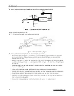
Page 20: ...cable to the 2 prong connector labeled POWER on the modem 2 Route the free end of the cable to the vehicle battery If necessary drill a hole in the vehicle firewall and route the cable through it using the supplied grommet Refer to Figure 6 Modem Power Wiring Diagram on page 14 3 Locate an available chassis ground mounting point near the battery and shorten the black lead to remove any excess cabl...

Page 21: ...9 pin male to a 9 pin female serial cable s The following step describes how to connect the data cable 1 Connect the 9 pin male end of the cable to the iR1200 MODEM communication connector and the 9 pin female end of the cable to the data terminal equipment DTE 2 Connect the 9 pin male end of the cable to the iR1200 GPS communication connector and the 9 pin female end of the cable to the data term...

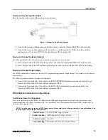
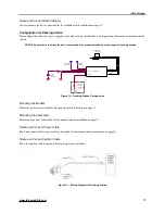
Page 22: ... Cable Route and connect the DC power cable as described for the standard mobile installation on page 14 Route and Connect Ignition Cable Route the ignition cable using the following diagram as a guideline Figure 9 Wiring Diagram for Continuous Power 1 Connect the male end of the ignition cable to the 4 prong connector labeled IGNITION on the modem 2 Connect the free end of the ignition cable to a...

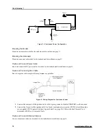
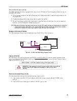
Page 23: ... DATA RS 232 MODEM DATA 12VDC FUSED MODEM ANTENNA 12VDC VEHICLE BATTERY GPS ANTENNA OPTIONAL DOCKING STATION CONTROLLED POWER iR1200 FUSE IGNITION POWER Figure 10 Docking Station Configuration Mounting the Modem Mount the modem as described for the standard mobile installation on page 11 Mounting the Antenna s Mount the antenna s as described for the standard mobile installation on page 12 Route a...

Page 24: ...p MDT docking station see Figures 10 and 11 on page 17 This circuit shall nominally output 12Vdc 5mA when the modem is intended to be ON and 0Vdc open circuit when the modem is intended to be OFF Route and Connect Antenna Cable s Connect the antenna cable s as described for the standard mobile installation on page 15 Route and Connect Data Cable s Connect the data cable s as described for the stan...

Page 25: ...ide Route and Connect Power Cables route the power cables from modem to the power supply Connect Antenna Cable s Connect cables to the mounted modem and antenna Connect Data Cable s Connect the data cables from the modem and GPS to the mobile device Mounting the Modem The iR1200 modem can be mounted on different types of surfaces You should determine if the surface is able to support the weight of...

Page 26: ...iR1200 modem Use of unapproved components violates the modem s warranty Select Antenna Location The antenna must be positioned where it has direct line of sight to the sky In some cases this can be accomplished by placing the antenna adjacent to a window In most cases it will require mounting outside of the building The cellular antenna s used for this transmitter must not be co located or operate...

Page 27: ... Cables The following diagram illustrates typical installation wiring of the iR1200 in a fixed environment COMPUTER RS 232 GPS DATA RS 232 MODEM DATA 120VAC TO 12VDC POWER CONVERTER MODEM ANTENNA IGNITION BYPASS PLUG GPS ANTENNA OPTIONAL POWER IGNITION iR1200 Figure 12 iR1200 Installation Wiring Diagram Fixed Approved Cables The following DC power cable was designed specifically for use with the i...

Page 28: ...e modem Route and Connect Data Cable s The iR1200 modem can be connected to the host DTE equipment using a standard straight through 9 pin male to a 9 pin female serial cable The following steps describe how to connect the data cable 1 Connect the 9 pin male end of the cable to the iR1200 MODEM communication connector and the 9 pin female end of the cable to the data terminal equipment DTE 2 Conne...

Page 29: ...gnal has been found and the modem has successfully connected 4 The STATUS LED should blink Green within 3 minutes from the time the vehicle s ignition was turned ON Powering Up Fixed Installation To turn on the iR1200 modem an ignition signal is required at the ignition connector Use the ignition bypass plug to simulate an ignition signal to power up the modem The following table lists the steps f...

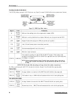
Page 30: ...f the modem status changes from blinking green back to solid red the signal has been lost and the modem is attempting to re acquire NOTE If after a period of several minutes the status does not return to green you may be out of range The modem will attempt to re acquire automatically when you are back in range NOTE STATUS indicators differ depending on the type of mode the modem is operating in Th...

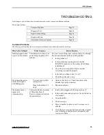
Page 31: ... bypass plug inserted into the IGNITION connector on the modem for building installations Check the power supply and make sure that everything is connected properly Is the battery voltage at least 12 volt Check the cables and wiring The modem has power but the LED light is not blinking green You may not be within coverage area Signal strength may be weak Antenna may be loose Check to make sure the...

Page 32: ...after power is applied to the iR1200 or immediately after the Reset button is pressed Diagnostic Port The diagnostic port located on the front panel of the iR1200 modem see Figure 13 on page 24 is used to retrieve data from the modem that will help to analyze and diagnose possible communication issues The following table describes steps to connect to the diagnostic port 1 Insert the 9 pin male end...

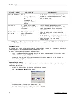
Page 33: ...he COM1 Properties screen appears 8 Select the following parameters from each of the drop down lists on the Port Settings tab 19200 for Bits per second 8 for Data bits NONE for Parity 1 for Stop bits None or Hardware for Flow control 9 Click OK when all the parameters have been selected 10 Once the connection to the modem is successful the iR1200 Rugged Modem Diagnostic Menu appears ...

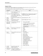
Page 34: ...l Strength This determines the signal strength of the modem Signal strength can be 0 100 5 Packet Data Registration Information This will check for packet data registration status Service type PACKET VALID NEI IP Address of the Modem Registration Status REGISTERED or UNREGISTERED MIP Registration Status REGISTERED or UNREGISTERED 6 Channel Information This determines if channel data has been obtai...

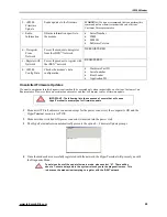
Page 35: ...uted only when instructed by an eLutions Customer Care Representative However there are certain sequences of events that will prompt you for a firmware update IMPORTANT The following lists the sequence of events that will cause HyperTerminal to prompt you for firmware update 1 Modem is OFF all cables are connected except for the power connector the computer is ON and the HyperTerminal session is A...

Page 36: ... compliance with FCC s national standards and guidelines regarding exposure of human beings to radio frequency electromagnetic energy Medical and Personal Electronic Devices Most electronic equipment are protected from RF energy However certain equipment may not be shielded against the RF signals being emitted from your modem Pacemakers Operators should not use the modem if individuals with pacema...

Page 37: ... 29 diagnostic port 27 dimensions 10 DNS IP Address 29 DSR 25 DTR 25 E Electronic Devices 31 F FCC 13 21 Firmware Update 30 Flow control 28 G GPS 6 14 22 H Hearing Aids 31 Heat 9 human body 13 21 HyperTerminal 27 I iDEN 6 ignition signal 24 M Master Reset 29 MCX 14 22 Mini UHF 14 21 Modem Pass Thru Mode 29 modem s dimensions 10 P Pacemakers 31 Packet Data 6 29 Parity 28 R Radio Frequency 31 Radio ...

Reviews: