background image

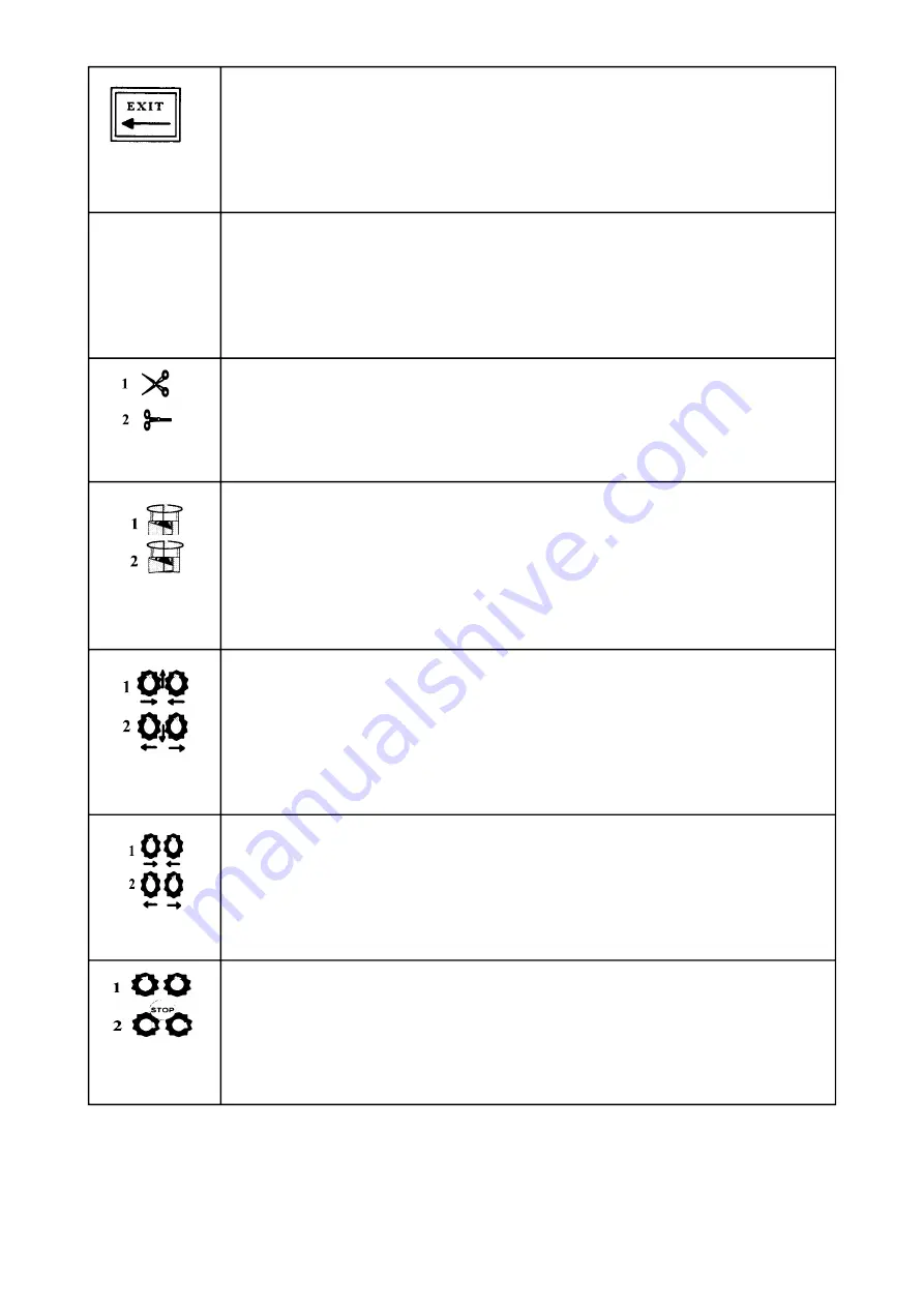
When in “SET” mode, this is used to exit the “SET” mode in order to reenter 
the operative mode. 

Allows for adding extra film layers to the bale both during the wrapping cycle 
and at cycle restart. During the cycle one push will cause the required number of 
film layers to increase by 1, two pushes 2 additional layers etc. Is the button 
activated after the cycle is completed but before offloading of the bale, one push 
followed by a RUN command will cause the cycle to restart and apply a 
minimum number of 2 layers in order to control the cutting device. 

Activates the film cut/ hold devices for manual operation. The manual operation 
of the device is not accessable during an automatic operation. 

1:Activates the WRAP ARM for manual operation. The wrapping will 
commence in slow speed and then accelerate to fast speed. When the manual 
wrapping is completed the speed will return to slow after which the wrap arm 
will stop. The wrapping will only remain while the FUNCTION SWITCH is 
activated. 
2: Activates the WRAP ARM for manual operation in slow mode. The 
wrapping will only remain while the switch is activated. 

1: Moves the rollers inward, bale loading. 

2:Moves the rollers apart, bale offloading. 

1: MANUAL bale LOADING function is operated via this switch. 

2: MANUAL bale OFFLOADING function is operated via this switch. 

1:Bale lifting. 

2: Bale rotation. 

* Emergency stop: see chapter 2.1

17 

Summary of Contents for AUTO WRAP 1200 EH

Page 1: ...MOUNTING OF PLASTIC FILM 15 7 0 REMOTE CONTROL UNIT CR 900 16 8 0 SPEED SETTING OF THE WRAPPING ARM 22 9 0 ADJUSTING THE OVERLAP 23 10 0 OPERATION INSTRUCTION 24 11 0 12 0 PERIODIC MAINTENANCE 26 13...

Page 2: ...pping machine 1 Wrapping arm motor 7 Main frame 2 Wrapping arm 8 Speed control 3 Prestretcher 9 Stationary arm 4 Rollers 10 Lifting sling 5 Support rollers 11 Emergency stop 6 Cutter 12 Safety guard E...

Page 3: ...be a reference for maintenance and troubleshooting So take good care of the books they are a part of the machine Read carefully through this manual and specially chapter 2 0 safety instructions befor...

Page 4: ...an emergency stop because it does not shut down the inputs But it has the same function so we have decided to call it an emergency stop in this manual 2 2 BECOME FAMILIAR WITH THE OPERATIONS OF THE M...

Page 5: ...ined we have a wrapping arm with a prestretcher and a plastic roll Once every time around this wrapping arm passes the main frame Here there may occur a squeeze danger if a person stands to close to t...

Page 6: ...used if this cover is removed or damaged 6 SQUEEZE DANGER BETWEEN TELESCOPE FRAME AND MAIN FRAME OUTWARDS On both ends of the telescope frame there can occur a squeeze danger when loading a new bale K...

Page 7: ...y working implements often has an overall negative effect on the tractor s driving and braking capacity 2 9 TRANSPORTING When transported on a public road there are certain safety measures that must b...

Page 8: ...rt rollers almost disappear into the bale the machine should be pressed down slightly at the rear edge in order to remove the bale from the machine The plastic can be damaged when friction against the...

Page 9: ...loose and misshapen bales with low solid content should not be stacked higher than one layer as this could easily cause deformity and the danger of runoff will be increased Bales can also be stored on...

Page 10: ...sure the machine is level across the tractor Tight up and lock the lifting arms so there is no sideways movement 4 2 TOP LINK Adjust the top link of the tractor so that the machine is level with the...

Page 11: ...t to recommend To secure the electric system against short circuits there is an 10A fuse on the plus leader near to the battery pole BROWN LEADER GOES TO BATTERY PLUS POLE BLUE LEADER GOES TO BATTERY...

Page 12: ...ressure the tractor gives or what oil pressure the balewrapper receives please contact your machinery dealer Generally all tractors have got some counter pressure in their hydraulic return systems Som...

Page 13: ...frame during transport Fig 4 5 7 Make sure that the plug in contact from the remote control is connected to the socket on the machine 8 Start the tractor and try out the functions A bale is not requi...

Page 14: ...tested you start the wrapping arm Hold out an arm or any obstacle The wrapping arm shall now stop before it hits the arm 5 6 To restart the machine the obstacle must be removed and the safety guard m...

Page 15: ...TTER OPEN 5 on the remote control block Pull out the film and place it over the U shaped slot 6 5 Push the CUTTER CLOSED button 4 and the film will be held in the U shaped slot 6 6 HEIGHT ADJUSTMENT O...

Page 16: ...in terms of facilities service and operation THE DISPLAY UNIT AND PANEL FUNCTIONS FUNCTION DESCRIPTION PRESELEKT The menu scroll up down key Is used for the mode the operator wishes to view It is also...

Page 17: ...or manual operation The manual operation of the device is not accessable during an automatic operation 1 Activates the WRAP ARM for manual operation The wrapping will commence in slow speed and then a...

Page 18: ...le when in standby mode STANDBY MODE Standby mode is the waiting state between the Auto and the Manual mode Standby mode is automatically resumed when 1 An automatic cycle is completed 2 Between cycle...

Page 19: ...s which enables the operator to perform various tests and adjustments to the machine operation Should adjustments of parameters which are not accessable to the operator be required please contact the...

Page 20: ...quired for display messages may be chosen if available via this meny AUDIOALARM DISPLAY Press SET to enter The contrast adjustment needed depends on the viewing angle and the light conditions in the c...

Page 21: ...to 25 WRAP CYCLE 0 To exit programmation of required film layers 25 0 push the EXIT button The balecounter number BALES 1 324 in this case counter number 1 will then flash and the counter number is n...

Page 22: ...hree seconds per revolution The adjustment is carried out by turning the wheel on the control valve Turning clockwise REDUCES the speed and turning counterclockwise INCREASES the speed It is recommend...

Page 23: ...valve for wrapping arm speed See chapter 8 3 When the wrapping arm speed is OK you can set the overlap 9 2 OVERLAPPING Use a black marker to mark a line on the middle of the film wrapped on the bale...

Page 24: ...the plastic film end is in the slot push START 8 and the wrapping arm now moves at speed for approx one half revolution before it automatically switches to full speed This is to avoid damage of the fi...

Page 25: ...RS OUT 7 and the bale will rest on the ground Drive the tractor carefully away from the bale Try to avoid touching the bale with the rollers The plastic film will now tear off by the perforation at th...

Page 26: ...st completely squeezed together when the cutter arm is all down 12 4 GEAR OIL The oil in the gearbox for the rollers must be exchanged after the first 100 working hours and after that every 2000 hours...

Page 27: ...st be greased regularly 12 10 SKIDDING RINGS Skidding rings and brushes for the emergency stop have to be cleaned up regularly Use alcohol or electric contact spray If necessary rub off the rings with...

Page 28: ...en e g START is pushed the wrapping arm motor starts at speed After a preprogrammed time it switches over to full speed After approx two revolutions it releases the film end and switches over to speed...

Page 29: ...ractors with variable oil pump like John Deere the crane handle must be closed Pos 10 fig 4 2 Then the oil can only come into the main valve block by operating one of the functions The closed centre v...

Page 30: ...the wrapping arm motor AUTO WRAP 1200 EH NUMERICAL ORDER OF THE MAGNET VALVES The numbers of the magnet valves are identical with the corresponding numbers on the electric leaders Valve for CUTTER Val...

Page 31: ...btained by the mounting of a nozzle inside the fitting to the brake a Non return valve It shall prevent the oil of going back to the control valve for wrapping arm speed It is placed inside the block...

Page 32: ...return valve which prevents oil from flowing to the wrapping arm motor when rollers width is operated When rollers out are operated the oil flows from the minus side of the width cylinder and through...

Page 33: ...you need more power to operate the valves MAX ALLOWED COUNTER PRESSURE IS 10 BAR If you are in doubt about the counter pressure arrange a free return directly to the tank If the counter pressure goes...

Page 34: ...to the main functions Pos 1 5 fig 14 2 If the electric supply is in order and one of the functions falls out the reason can be a mote that tights or prevents the sliding shaft to open and or close Tr...

Page 35: ...be removed so that the wrapping arm can move free b The safety valve S3 fig 14 4 can be leak so that the oil is passing by the wrapping arm motor Dismantle and try out if the sliding shaft can move fr...

Page 36: ...eak out through this valve so the roller motors are losing their power To be able to loosen possible mote the valve can be operated manually with a screwdriver at the end of the valve See chapter 16 2...

Page 37: ...C CHART NORSE AUTO WRAP 1200 EH RIGHT ROLLER MOTOR OILFILTER LEFT ROLLER ROLLER MOTOR SPEED DOWN CUTTER UP TWO STEPS SPEED IN WRAPPING ARM MOTOR WIDTH OUT WRAPPING ARM SPEED Emergency stop see chapter...

Page 38: ...in Guarantee claimed parts also have to be enclosed All return shall be agreed upon before sending and marked with serial number on the machine and the name and address of the dealer Freight costs for...

Page 39: ...erial number of machine Type Serial number of control unit Production year Purchase date WE HAVE READ AND ACCEPT THE CURRENT WARRANTY TERMS Importer Date Firm Signature Dealer Date Firm Signature Cust...

Page 40: ...HAVE YOU GOT ENOUGH TRAINING ABOUT THE MACHINE FROM YOUR DEALER YES NO 44...

Page 41: ...45...

Reviews: