Telink FR1 PCB Design Guideline
AN-22051900-E1 Ver. 1.0.0
19
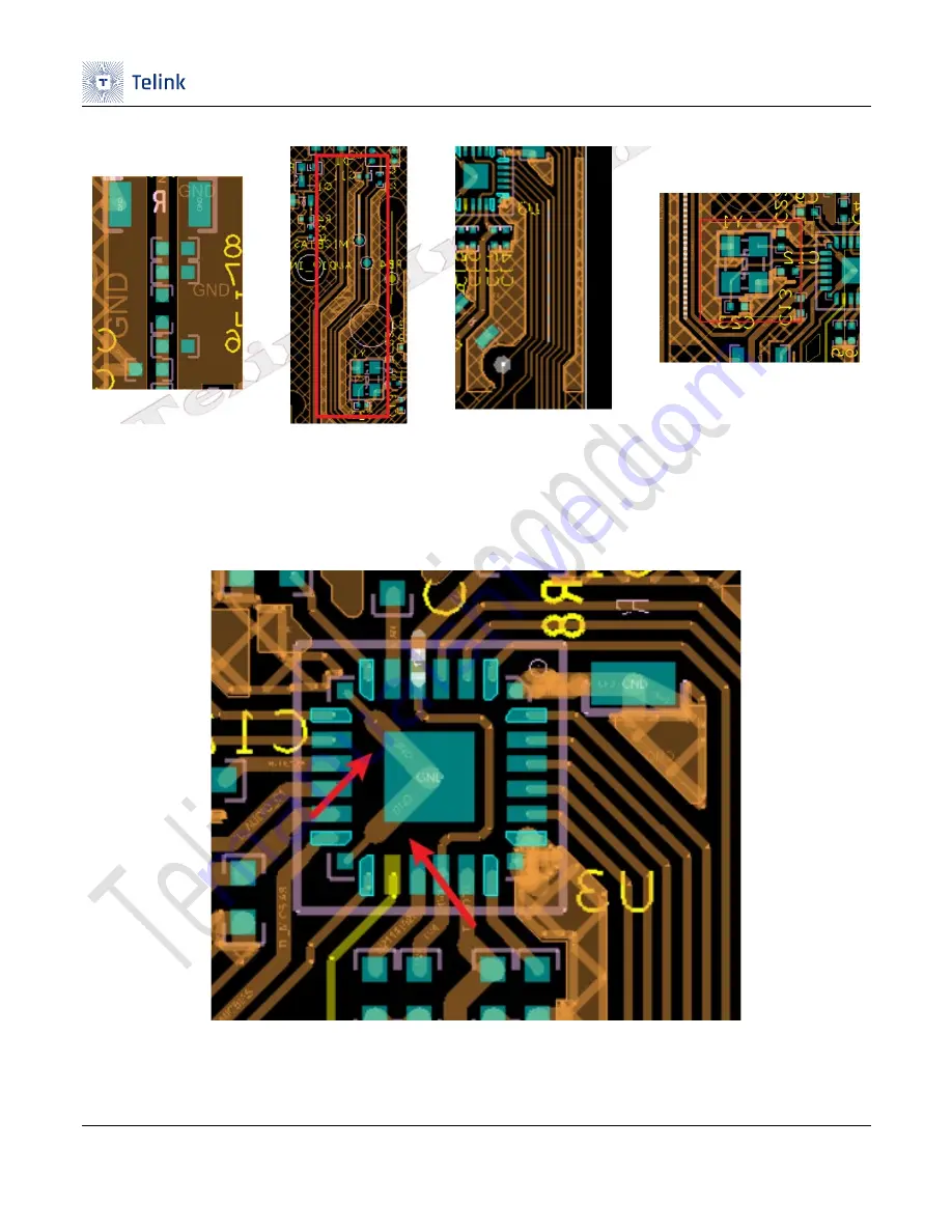
Figure 5-1 Routing example 1
In order to make a good connection between the chip and the ground and improve the RF performance,
it can be connected to the system ground through the chip's four corner ground, as shown in the location
of the red arrow in Figure 5-2.
Figure 5-2 Routing example 2


