ES
15
5.Splicing process
5.1 Electrode and element inspection
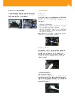
Make sure there is no trace of fibres/dirt on the electrodes,
v-groove, lenses or mirrors . Check the correct alignment of
the electrodes and make sure their ends are in good sha-
pe . Should you find any impurities, take them away with a
wipe/swab dampened with isopropyl alcohol .
5.2 Fibre preparation
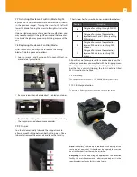
- Strip the fibre with the help of a stripper . The stripped
length should be 30 mm to 40 mm . With isopropyl alcohol,
clean any protection residues that may have remained on
the fibre and put it on the cleaver (make sure the fibre is as
straight as possible between both rubbers) .
Depending on the fibre type you will be using, you will
need to place the fibre in a specific rail, as shown below:
Rail
Type of use
Upper rail
For single-fibre tubes (3mm thick) or BIF
tubes .
Intermediate
rail
For fibres with an initial thickness of
900 microns (see example on the image
below) .
Lower rail
For fibres with an initial thickness of 250
microns .
- Proceed to cutting the fibre with the cleaver . Leave ap-
proximately 16mm of fibre uncovered after cleavage (see
picture) .
In case you were not able to perform the cleaving, check
and make sure that:
1
Both fibre protections are correctly removed (900 and
250 microns) .
2
The cutting blade is neither worn out nor marked .
3
The cutting blade's height is correct (the blade should
slightly protrude over the fibre-holding rubbers) Should
this height be incorrectly set, you can modify it with the
screw .
Make sure that the fibre sitting on the cleaver do not form
an angle between both holding rubbers, since it could
cause problems for the fusion (higher cutting angle) . Fibre
should sit on both runners, always forming a straight line
between both . The following example illustrates how NOT
to place the fibre .
5.3 Fibre type
Switch on the fusion splicer and select the fusion program-
me based on your fibre type . For single-mode fibres, the
manual SM mode is pre-set by default .


