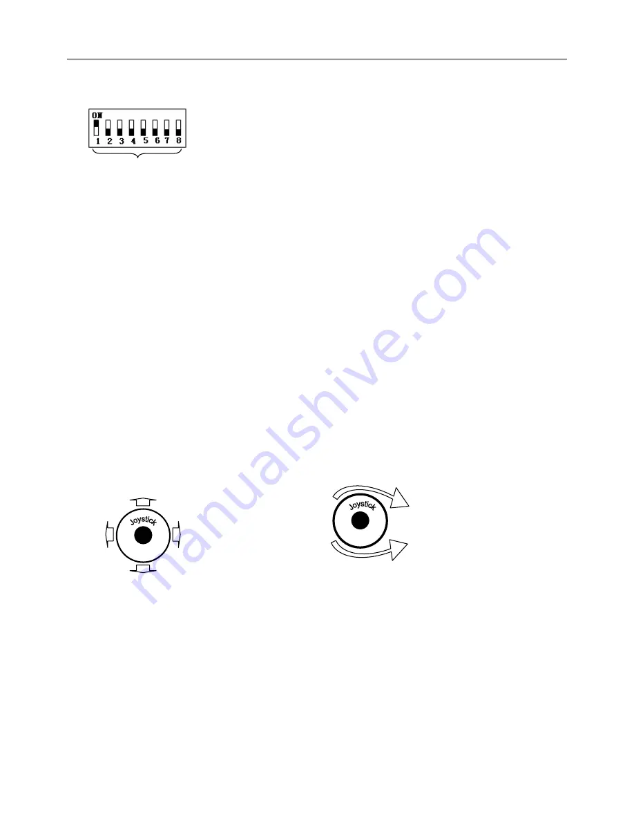
TeleEye DM597 User Manual Download Page 14


                                                                                                                                                                                                                      V1.1 

13


III. 

Setting dome device address.

 (Turn the power off when setting, and restart the device after revision). 


The figure shows: Address of the dome device: No. 1


(Please refer to detailed parameter in next chapter) 


This dip switch located on PCB in the dome device 


IV. Install camera.

 (Please refer to camera installation for details). 

      Attention: 1

.

 Do not connect the camera and dome device with FFC in a wrong way. 


2. The installation holes of different camera differ.


V. Connect the power of dome device. 


At this moment, the self-test (rotation) of dome device and self-test (there will be image on the monitor) of camera can be 

seen. 

      Attention: When the dome device is self-testing, it is normal when sound is issued caused by the block of dome device after 

2~5 seconds of vertical movement, which is the tilt orientation of the dome itself. 

VI. Controller setting. 

Set the protocol, baud rate and address of the keyboard controller identical with those of dome device. 

(Please refer 

to keyboard controller instruction manual). 


Attention

:  If  the  setting  of  protocol  of  dome  device  is  auto  detection,  the  protocol  of  keyboard  controller  can  be  set 

arbitrarily. But its baud rate should be set identical with that of the dome device. 

VII. Start testing. 

    When all the above are ready, the testing to dome device can be started. 


1. Direction control test of dome device                  2. Zooming control test of camera 


The directions (up, down, left and right) of the                      Zooming of the camera can be controlled by   

dome device can be controlled by using the                            zooming function Joystick or by using TELE (zoom in)     

keyboard controller, as indicated in the figure.                        and WIDE (zoon out) on the keyboard button.     

Note:

 the working of dome device is normal                               

Note: 

The camera and dome device are normal             


Please refer to the next section for demonstration of menu operation and control of dome device.


VIII. Complete the test.

 (Summary). 

1. If the performance of item 7 is normal, it indicates the system is basically normal. Please do not change the wiring and 

various setting to avoid fault and unnecessary damage and loss. 

2.  If  the  performance  of  item 7  is abnormal, or  only  one  item  works  normally,  please check  the  wiring  (item 1 and  4)  and 

setting (item 2, 3 and 6) carefully. 

Set address for

 dome 

u

p


d

o

w

n


L

e

ft

ri

gh

Zoom in 

Zoom 

out 

R

ot

at


Summary of Contents for DM597

Page 1: ...V1 1 User Manual TeleEye DM597 DM599 High Speed Dome Before attempting to install or operate on this produce Please read this manual carefully and keep it for future use...

Page 2: ...ID 11 Chapter Three Fast Operation Guide of Dome Device I Wiring 12 II Setting protocol and baud rate 12 III Setting dome device address 13 IV Install camera 13 V Connect the power of dome device 13 V...

Page 3: ...t the view angle can be 90 or 92 degree 5 Pan manual operation speed can be 0 1 to 280 degree per second 6 Tilt manual operation speed can be 0 1 to 120 degree per second 7 128 pershot positions A fix...

Page 4: ...gentina CAMERIO is a trademark of Signal Communications Limited and is registered in Australia Japan Korea New Zealand Taiwan and Argentina All other trademarks are the property of their respective ow...

Page 5: ...oof and other protecting measures should be carried out 6 Please avoid exposing the Dome video camera to rain or the humidity etc Please do not use the product in humid place If the video camera is in...

Page 6: ...crew holes Fig III 1 Fig III 2 Step one Aim the open end of shield dome at the lens of camera Aim the 4 holes on the shield to the 4 M3 screw holes on the dome device as indicated in figure III 2 Step...

Page 7: ...ded to wear cotton gloves when operate 2 As shown in the figure below first take the flexible flat cable through connector above the base plate and buckle it on the connector Then buckle the cable on...

Page 8: ...V1 1 7 V Install Bend Tube Style Bracket Fig V 1 Connecting the dome to the wall mount with the bracket Fig V 2 Wall mount bracket installation...

Page 9: ...ce is power on 2 Multi dome device connection When connecting many dome devices together the user can embed multi device system with auxiliaries such as arrester device video matrix DVR and alarm box...

Page 10: ...e On Off status Protocol type 1st digit 2nd digit 3rd digit 4th digit 5th digit 6th digit PELCO D ON ON OFF OFF PELCO P OFF OFF ON OFF TeleEye DM2 ON ON ON OFF Dome device controller Image displayer P...

Page 11: ...0 OFF OFF 4800 OFF ON 9600 ON OFF 19200 ON ON This figure shows protocol of PELCO D Baud rate of 2400 Setting address for dome device this figure shows the address of dome device No 1 On Off switch Se...

Page 12: ...V1 1 11...

Page 13: ...s Protocol PELCO D Baud rate 2400 bps Please refer to detailed parameter in next chapter This dip switch located on PCB in the dome device Protocol setting Baud rate setting Image displayer Cables RS...

Page 14: ...ing of protocol of dome device is auto detection the protocol of keyboard controller can be set arbitrarily But its baud rate should be set identical with that of the dome device VII Start testing Whe...

Page 15: ...reshot setup options 1 Numder 1 Preshot number selection Press OPEN or Joy stick left or right to enter The default number after entering is 001 hundred bit ten bit single bit Joy stick left or right...

Page 16: ...CLOSE When Done _ _ _ _ _ _ _ _ 0 1 2 3 4 5 6 7 8 9 A B C D E F G H I J K L M N O P Q R S T U V W X Y Z _ IRIS CLOSE When Done IRIS CLOSE When Done IRIS CLOSE When Done Press OPEN or joystick left or...

Page 17: ...ft or right to enter 1 Default Function P V T Select default function Preshot Tour PTZ Press OPEN or Joy stick left or right to enter 2 Number 1 Function number selection Press OPEN or Joy stick left...

Page 18: ...estore default setting Press OPEN or Joy stick left or right to enter 3 Color system PAL NTSC PAL NTSC switch Joy stick left or right to select 4 Scan Camera Reset Null Restart dome camera Press OPEN...

Page 19: ...2 Change Name Loc Change display location of name Press OPEN or Joystick left or right to enter 3 Name Display ON OFF Name display On Off Joystick left or right to select IRIS CLOSE to Exit 4 Mask Se...

Page 20: ...to enter 3 Program a Tour Enter PTZ tour programming Press OPEN or Joy stick left or right to enter 4 Run a Tour Run Pan Tilt Zoom tour pattern Press OPEN or Joy stick left or right to enter 5 Delete...

Page 21: ..._ _ 16 IRIS CLOSE When Done Joystick arbitrarily to move the cursor and stop the cursor at place of programming Press OPEN to enter the selection Press OPEN continuously to select P Preshot T self stu...

Page 22: ...alarms Press OPEN or Joystick left or right to enter This function is not available at the moment Name Num E N 1 _ _ _ 2 _ _ _ 3 _ _ _ 4 _ _ _ IRIS CLOSE to Exit P V T 1 128 0 0 1 2 3 4 5 6 7 8 9 IRIS...

Page 23: ...on and focus 3 Input the preset number 4 Press ENTER 5 Repeat step 2 to step 4 if you want to set more preset point 6 Press set key to exit Call Preset N PRESET 1 Input the preset number 2 Press ENTER...

Page 24: ...ate is slow If S is within 81 160 the scan rate is medium If S is within 161 250 the scan rate is high Focus Control Generally the camera will automatically adjust the focus to get clearer image based...

Page 25: ...ronic signal noise or the camera is directed to the monitor screen Grounding the dome device or shut off the surrounding big electronic devices electric HF signal generating equipment or rotate the ca...

Page 26: ...ce transmission Add driver Improper contact of control cable Check the circuit slip ring is demage Replace slip ring 10 Insensitive control of dome device RS 485 protective discharge arresters broken...

Reviews: