18
Teledyne API Model 480L O
3
Monitor User Manual
09419A DCN8342
3.4.1 ANALOG OUTPUT
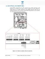
Refer to Figure 3-4 for the location of the analog output, which can be configured
for 0-5 V voltage or 4-20 mA current output. See Section 3.4.1.1 for details on
verifying or changing the analog output hardware configuration.
The analog output is automatically scaled to the range of the instrument. See
Section 5.2.4.1 for information on changing the range of the monitor.
The monitor has an analog output step-test mode that can be used for verifying the
operation of the analog output and calibration of external measurement equipment.
This mode is described in Section 5.2.3.1.
3.4.1.1
A
NALOG
O
UTPUT
H
ARDWARE
V
ERIFICATION OR
C
ONVERSION
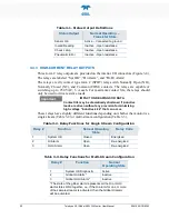
To change or verify the configuration of the analog output, refer to Figure 3-5 while
performing the following instructions:
1.
Disconnect power from the monitor.
2.
Open front panel.
3.
Locate J15 and J17 connectors on the Mainboard PCA (remove Relay
Expansion board if installed as indicated in Figure 3-5).
4.
Set the desired output as shown in Figure 3-5 where:
•
for Current output (4-20 mA), jumper Pins 1-2 on both J15 and J17, or
•
for Voltage output (0-5 VDC), jumper Pins 2-3 on both J15 and J17.
5.
If applicable, reinstall/connect Relay Expansion board.
6.
Re-secure the front panel.
7.
Reconnect power to the monitor.
Summary of Contents for 480L
Page 2: ......

