background image

SI-125 Power Amplifier Manual 


Clipping 

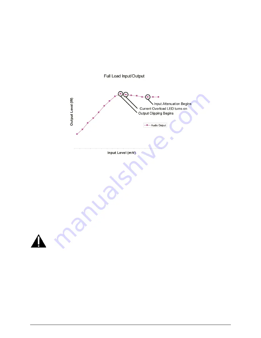
Output Clipping

 is the point where the peak output signal is limited to avoid damage to the 

amplifier from excessive output current (current overload). Once output clipping is detected, any 
increases in input level will not cause increases in output level (this is shown by the output 
plateau in Figure 4). To avoid distortion, the output signal is dynamically attenuated to give the 
maximum attainable output voltage without distortion, although technically the peak output level 
is clipped at this point. The Current Overload light will turn on when the current limiting 
circuitry is engaged. 


Figure 4: Effect of Clipping 

Input Attenuation

 will occur when the signal is limited due to excessively high signal level at 

the input. The clipping LED will turn on either when there is excessive signal level on the input 
or when there is hard clipping present on the output. The CLIP light will not turn on when the 
output level is clipped due to current overload. 

Installation 

Before installing an SI-125 Power Amplifier, carefully inspect the device for any damage that 
may have occurred during shipping. The shipping package should contain only the Power 
Amplifier. If any part of the amplifier has been damaged, please contact the shipping company as 
soon as possible. 


DO NOT ATTEMPT TO INSTALL EQUIPMENT THAT WAS RECEIVED
DAMAGED.


The amplifier mounts into a standard 19" Telecor equipment rack with 10-32 screws. The SI-125 
requires 5 ¼" of vertical rack space. When mounting the amplifier into a rack with other 
equipment, be sure to allow for adequate ventilation. To accomplish this, ensure that a blank 
panel of 1 ¾" height (or greater) is installed between the amplifier and any other equipment (e.g. 
additional amplifiers, power supplies, etc.) in the rack. 

Summary of Contents for SI-125

Page 1: ... from overloading The amplifier also has circuitry to protect it from overheating The SI 125 Power Amplifier can have optional modules installed for additional functionality The PA AM Power Amplifier Attenuator Module allows the amplifier to support a 25 V input signal The PA MM Power Amplifier Monitor Module activates a relay under normal amplifier operation The PA PM Power Amplifier Paging Modul...

Page 2: ...ee the Troubleshooting section C CURRENT OVERLOAD Light If the current output of the amplifier exceeds its maximum power output the Current Overload light will illuminate and the output level will begin to be reduced The amplifier will continue to operate with the current limiting circuit reducing the output power If the Current Overload light illuminates see the Troubleshooting section D GAIN Con...

Page 3: ...overs the slot Please note that the accessory modules are not user installable They must be factory installed and ordered with the amplifier Do not remove any modules or the cover plate J INPUT LEVEL Switch The Input Level switch selects the range of the input level This switch works in conjunction with the GAIN Control on the front of the amplifier The Input Level switch should be set to match th...

Page 4: ...urn on either when there is excessive signal level on the input or when there is hard clipping present on the output The CLIP light will not turn on when the output level is clipped due to current overload Installation Before installing an SI 125 Power Amplifier carefully inspect the device for any damage that may have occurred during shipping The shipping package should contain only the Power Amp...

Page 5: ...own in Figure 5 Figure 5 Input Connections To reduce the incidence of ground loop hum oscillation or interference from other audio sources 1 Use a shielded cable for input wiring The shield must be grounded at one end of the cable only not both 2 Regardless of what type of input signal is supplied to the amplifier balanced or single ended the GND terminal should not be connected to the common term...

Page 6: ...pplications there is often a privacy switch in the room When this switch is activated it grounds one side of the room speaker line through a transformer Make sure that all these privacy switches are not in the Privacy position when measuring line impedance to ground These switches do not adversely affect the operation of the amplifier When measuring load impedance on a Telecor installation disconn...

Page 7: ...registers a signal when no signal should be present The amplifier may be oscillating possibly at a very high frequency This may be caused by running input and output wires close together grounding the input or incorrect grounding of the shield The Current Overload light illuminates or flashes This indicates that the amplifier is being overloaded Check the total speaker load on the amplifier Also c...

Page 8: ...ls on input and output Mas Con connectors are used with optional modules Controls Power Switch Illuminated GAIN Control Low Cut Switch Input Level Switch 1 V 100 mV Indicators Clip High Temperature VU Meter and Current Overload Protection Foldback current limiting Over temperature protection Primary circuit fused at 3 5 A Temperature Range 10 C to 35 C 14 F to 95 F Power Consumption AC 120 V 60 Hz...

Page 9: ...ansportation labor charges indemnity etc are not covered by this warranty and no responsibility for same will be assumed by us Our liability does not extend to consequential damage AUTHORIZED REPAIR STATION All participating Distributors and Dealers are authorized to accept Telecor products for return to us for repair or replacement or customers may return goods to us directly providing that retur...

Reviews: