background image

Chapter 4 Installing the SIM card

The Regesta-PRO-ER routers have Wireless WAN interfaces that in order to operate may require at least one SIM
card that must be inserted into the device. There are determined services (CDMA) provided by some carriers in cer-
tain countries that do not require SIM cards.

The Regesta-PRO-ER routers have two SIM trays. Both trays are located inside the device casing and are labeled
SK1 and SK2.

In installations where only one SIM card is required, we recommend that it is installed in the main SK1 tray.

Warning

Never install the SIM cards when the device is switched on.

Always disconnect the device from the main power supply before installing the SIM cards.

Always disconnect the device before removing the casing to access the trays.

When inserting the SIM cards, please protect yourself against electrostatic discharges (ESD).

Do not touch the SIM cards connectors.

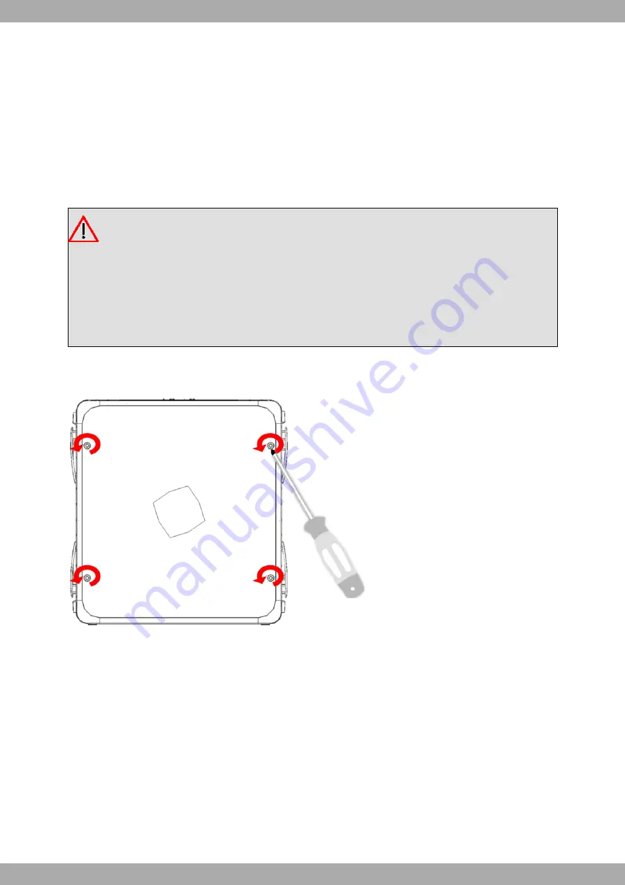
To access the SIM tray, you need to open the upper casing of the device. To do this, you need to undo the four
screws which are on the upper side of the device.

Fig. 20:

Screws on the upper casing

4.1 Identifying the SIM trays

Once you have removed the upper casing, you will be able to see the different elements illustrated below.

The Regesta-PRO-ER incorporates 2 SIM cards, which allow you to execute some special configurations. One ex-
ample is installing two SIMs and using one as a backup to the other. To carry out this type of configuration, you must
assign a tray to each SIM (since the latter require different configuration parameters).

The SIM trays are identified as SK1 and SK2 i.e. socket 1 and socket 2.

Teldat S.A.

4 Installing the SIM card

Regesta-PRO-ER

19

Summary of Contents for REGESTA-PRO-ER Series

Page 1: ...Regesta PRO ER Installation Manual Copyright Teldat DM480 I Version 4 2 7 2015 Teldat S A Teldat S A Manual Regesta PRO ER 1...

Page 2: ...dat S A offers no warranty whatsoever for information contained in this manual Teldat S A is not liable for any direct indirect collateral consequential or any other damage connected to the deliv ery...

Page 3: ...nents 6 3 1 1 Front Panel 6 3 1 2 Rear Panel 8 3 1 3 Underside Panel 9 3 1 4 Upper Panel 9 3 2 Assembly 10 3 2 1 Installing a DIN rail mount accessory 10 3 2 2 Installing the Protector 11 3 3 Power So...

Page 4: ...23 A 4 1 LAN Connector 23 A 4 2 DSL Connector 23 A 4 3 RF Connectors 23 A 4 4 Configuration Connector 24 A 4 5 Serial Port Connectors 24 A 5 Technical Specifications 24 A 5 1 LAN Interface 24 A 5 2 D...

Page 5: ...I Related Documents Teldat Dm748 I Software Updating Teldat Dm781 I Cellular Interface Teldat S A Related Documents Regesta PRO ER 1...

Page 6: ...Description of the general characteristics available in the Regesta PRO ER router family Technical Specifications Power supply requirements Description of the LEDs and the router connectors Troublesho...

Page 7: ...Email support teldat com Teldat S A 1 About This Guide Regesta PRO ER 3...

Page 8: ...as GPRS EDGE UMTS HSDPA HSUPA CDMA 2000 1xRTT CDMA Ev Do etc As for the LAN networks this device incorporates a 6 port 10 100 BaseT LAN Ethernet Switch The basic license en ables the first 2 ports By...

Page 9: ...ave an ADSL interface and the DSL connector is closed By default the device incorporates a transparent protector that prevents the connectors from being touched while the device is running Fig 1 Reges...

Page 10: ...ow the reset button works please see section RST Button on page 14 further on in this chapter This button is only available in version AC C 6 port Ethernet Switch D DSL ADSL connector permitting conne...

Page 11: ...s processing traffic through the carrier for the SIM in stalled in this tray C Cellular interface corres ponding to the active SIM or the statue of the ADSL con nection In cases where the router is eq...

Page 12: ...FF Connection at 10 Mbps LNK Associated to each Ether net switch connector LAN1 LAN6 Green ON Ethernet connection link established Steady light Data is not being transferred Flashing Data is being tra...

Page 13: ...DIN rail mount For further in formation on this accessory please see section Installing a DIN rail mount ac cessory on page 10 further on in this chapter B Platform where the sticker containing inform...

Page 14: ...g a DIN rail mount accessory The device packaging includes a DIN rail mount kit to which the device can be connected thus allowing various posi tions The kit contains 2 screws to adjust the rail mount...

Page 15: ...t protector protects the device connectors from being manipulated while the device is operating The protector is not mounted on the device in the package it is a separate piece The following figure sh...

Page 16: ...efore installing handling or opening the equipment covers connect and discon nect the cables following the steps set forth in To Connect on page 13 andTo Disconnect on page 13 3 3 1 Connecting to the...

Page 17: ...labeled ground that connects the device to the ground point where the rest of the devices are connected 3 3 3 Device powered with 220 V AC Fig 11 Power supply connection with external source 110 220...

Page 18: ...n the front panel lighting up in amber 2 Stop pressing the RST internal external button as soon as the 3 LEDs on the front panel are lit up 3 The device will begin the restart with LEDs S and C off an...

Page 19: ...ules MAIN internal connectors for both modules Whenever a device has just one WWAN module the RF1 connector is connected to the module s MAIN connector and the RF2 connector to the AUX connector in th...

Page 20: ...i crowaves etc can temporarily interfere with the quality of the wireless signal We do not recommend that you install the antennas near or between racks containing communication devices computers etc...

Page 21: ...22 2 operating mode uses reduced transmission power It allows the use of telephones directly connected to the same line through the installation of a micro filter This device ensures that the ADSL sig...

Page 22: ...in 3 and GND 5 5 DB 9 connector Fig 18 Console connector as serial port To use this as the router s configuration port please see section Connecting to the router on page 22 3 5 4 2 Asynchronous seria...

Page 23: ...oving the casing to access the trays When inserting the SIM cards please protect yourself against electrostatic discharges ESD Do not touch the SIM cards connectors To access the SIM tray you need to...

Page 24: ...eps are as follows 1 Push the fastening in the direction indicated by the arrow with the word OPEN 2 Open the upper part of the tray 3 Fully insert the SIM card using the guides 4 Return the tray to i...

Page 25: ...time in the device are lost on when restarted Parameters configured through the time set command will be lost when the device restarts Use the NTP protocol to keep the date and time configuration The...

Page 26: ...a DB 9 female connector on the front panel referred to as CONF which provides access to the device local console In order to configure this you must connect the CONF port to an asynchronous terminal...

Page 27: ...255 255 255 0 Connect the IP terminal Ethernet interface to any of the Regesta PRO ER router s Ethernet Switch ports LAN1 6 through the Ethernet cable RJ45 provided Initiate a Telnet session from the...

Page 28: ...3 4 5 6 7 8 CD RxD TxD DTR GND DSR RTS CTS A 5 Technical Specifications A 5 1 LAN Interface PROTOCOLS Ethernet 802 3 SPEED Switch 10 100 Mbps Base T CONNECTOR RJ45 female A 5 2 DSL Interface STANDARD...

Page 29: ...thout flow control CONNECTOR DB9 female on the front panel of the device A 5 5 Direct Power Supply INPUT VOLTAGE 48 V DC INPUT CURRENT 300 mA MAXIMUM POWER 15 W A 5 6 Alternating Power Supply INPUT VO...

Page 30: ...any additional steps established by law All the packing materials i e the cardboard box plastic and any other packaging together with the pieces making up a Regesta PRO ER must be recycled complying...

Page 31: ...B 2 Translated Safety Warnings To Connect To Disconnect 0123 14 0 12 5 6 7 4 52 7 5 78 9 23 1 00 5 6 7 9 5 7 5 7 9 9 3 4 5 7 3 9 5 7 3 Teldat S A Safety information Regesta PRO ER 27...

Reviews: