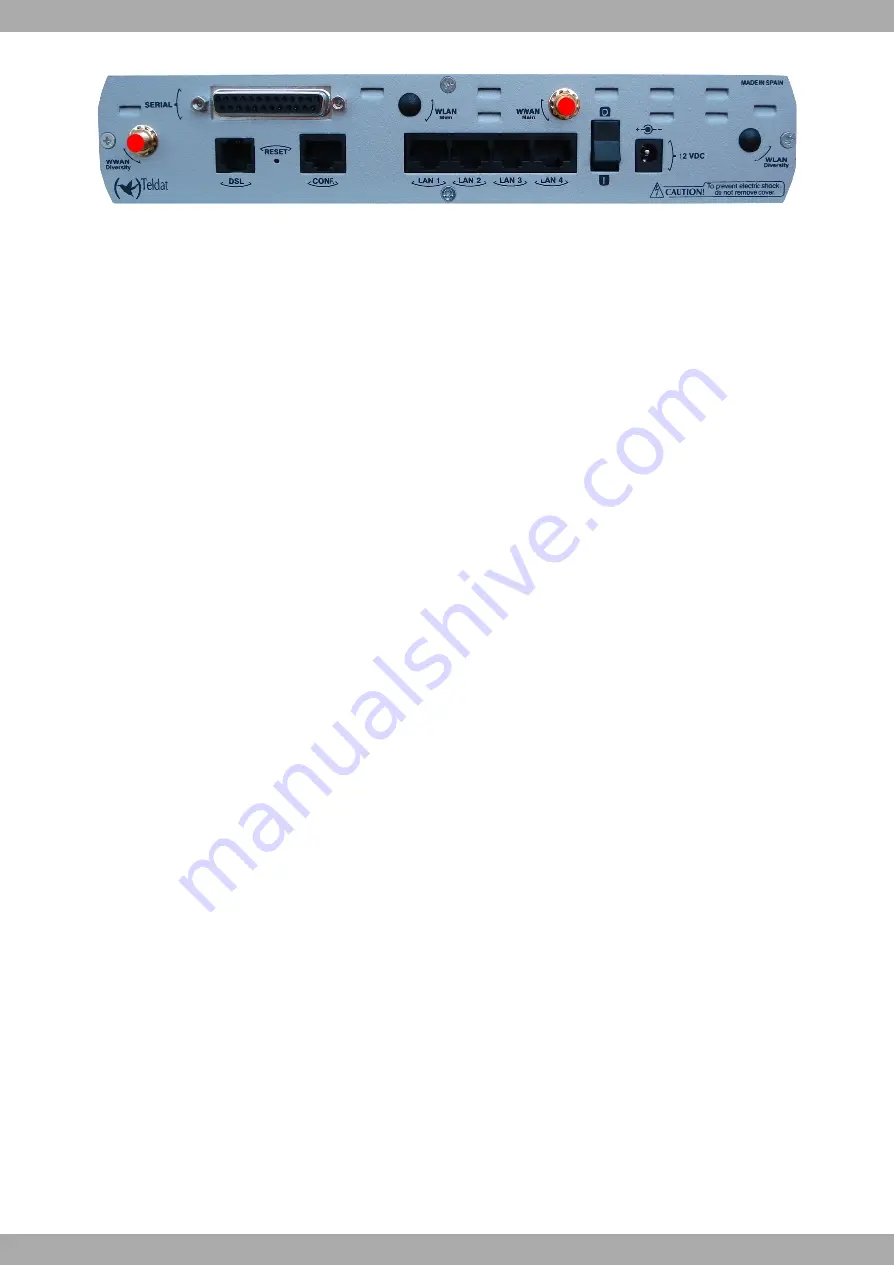
background image

Fig. 10:

Wireless WAN antenna connectors

If the Main and Diversity antennas are not directly connected to the device, but installed through extension cables,
the minimum distance between them must be 7cm and the maximum recommendable distance is 25 cm.

To achieve optimum performance from the installed radio frequency accessories (antennas and cables), these
should be the ones recommended by Teldat.

Teldat has a series of accessories (angled antennas, antennas for external use, ceiling antennas, extension cables,
etc.), which allow you to install the Teldat C1+LS in different locations.

Placing the antenna

The orientation of the antenna and its location with respect to other wireless devices and radiation devices (such as
communication devices, personal computers, etc.) can significantly influence the device performance.

The antennas transmit and receive radio signals. Performance is also affected by environmental factors such as the
distance between the device and the base station, physical obstacles and other interferences due to radio frequen-
cies (RF).

In order to achieve the best coverage, carry out the following instructions:

• Whenever possible, place the antenna where there are no physical obstacles. Obstacles between the Teldat-3Ge

and the base station degrade the RF signal. Place the device above ground level and ensure that it is suitably ori-
entated towards the nearest base station.

• Density of materials also affects the antennas. Place them away from any type of wall, metal screens, mirrors, etc.

• Do not place the antenna near columns that can produce shadow areas and reduce the coverage zone.

• Keep the antenna away from metal pipes such as canals, air-conditioning.

• Please bear in mind that other wireless devices such as telephones, microwaves, etc., can temporarily interfere

with the quality of the radio signal.

• We do not recommend that you install the antenna near or by racks containing communication devices, computers,

etc. Use an extension cable and place the antenna outside.

The following recommendations are applicable to all wireless devices:

• Do not touch or move the antenna while the device is transmitting or receiving.

• When the antenna is transmitting, do not touch any equipment that contains devices that radiate very close to, or

touching, any exposed part of the body (particularly the face and eyes).

• Do not install the device in areas where the atmosphere is potentially explosive.

• Wireless devices can cause interferences with other devices. Do not use the device in areas where medical equip-

ment is installed.

• In order to ensure that you are complying with the R&TTE 1999/5/EC norm, the device must be at least 15 cm

away from a human body when it is operating.

1.2.3 Configuration Connection

1.2.3.1 Configuration using a local console (CONF connector)

The Teldat C1+LS router has a female RJ45 connector on the rear panel labeled as “Conf.”, which provides access
to the device’s local console. For configuration, you must connect the “Conf.” port to an asynchronous terminal (or to
a PC with terminal emulation).

Teldat S.A.

1 Installing the Router

Teldat C1+LS Router

7

Summary of Contents for C1+LS

Page 1: ...Teldat C1 LS Router Installation Manual Copyright Teldat DM487 I Version 3 1 7 2015 Teldat S A Teldat S A Manual Teldat C1 LS Router 1...

Page 2: ...S A offers no warranty whatsoever for information contained in this manual Teldat S A is not liable for any direct indirect collateral consequential or any other damage connected to the deliv ery sup...

Page 3: ...e start up in BIOS mode 15 Appendix A Technical Information 18 A 1 Trouble shooting 18 A 2 Software Updating 18 A 3 Connectors 18 A 3 1 LAN Connector 19 A 3 2 DSL Connector 19 A 3 3 SERIAL Connector 1...

Page 4: ...Table of Contents Teldat S A ii Teldat C1 LS Router...

Page 5: ...device Warning The equipment is intended to be installed by Service Personnel and only handled by qualified person nel If not the device may be damaged and malfunction This device contains elements t...

Page 6: ...lay scenarios or with an external backup device The Teldat C1 LS router is perfectly adaptable to a wide variety of IP scenarios from providing simultaneous ac cess to Internet for private LAN users a...

Page 7: ...les telephone lines and communication cables is dangerous To pre vent electric shocks before installing handling or opening the equipment covers connect and discon nect the cables as follows To Connec...

Page 8: ...ents Fig 4 Connecting the power with an external source To connect the power source to the device follow the steps listed in the previous table make sure that the switch is OFF 0 and that the power su...

Page 9: ...o use a mechanism known as splitter to part the band frequencies for voice telephony from those used by the ADSL connection to transmit data This way interferences between the telephone service and th...

Page 10: ...nectors labeled WWAN located at the rear of the device You must install the antennas in the Teldat C1 LS router in order to improve the quality of the signal received and sent by the Wireless WAN modu...

Page 11: ...lace them away from any type of wall metal screens mirrors etc Do not place the antenna near columns that can produce shadow areas and reduce the coverage zone Keep the antenna away from metal pipes s...

Page 12: ...adapter isn t provided with the device it is supplied separately Fig 12 Connection for configuration 1 2 3 2 Configuration using an IP terminal connectors LAN1 4 The Teldat C1 LS router includes a de...

Page 13: ...CD supplied with the Teldat C1 LS router 1 2 4 Installing the SIM card The Teldat C1 LS has a Wireless WAN interface which means that at least one SIM card must be inserted in the device for it to wor...

Page 14: ...d The steps to follow are 1 Push the catch towards the left OPEN until the SIM card tray is released 2 Lift up the upper part of the tray 3 Fully insert the SIM card between the guides 4 Return the in...

Page 15: ...LAN1 4 LAN Ethernet Switch OFF The link has not been established in this port GREEN A link has been established in this port Intermittent Traffic in the port DSL DSL Interface SLOW FLASHING The link h...

Page 16: ...relicense and delete the configuration files 1 4 1 Procedure to ignore the current configuration and to establish the default configuration Follow the steps below when you have to reject the whole co...

Page 17: ...image 0xbe8a0000 Code Address 0x80010000 Entry Address 0x80330000 Booting version 10 08 00 00 00 Decompression OK Entry at 0x80330000 Closing network Closing DMA Channels Starting program at 0x8033000...

Page 18: ...ice has booted with the default parameters from the BOOT configuration and has paused start up in the BOOT menu CFE prompt CFE version 1 0 37 102 9 01 for BCM96358 32bit SP BE Build Date Fri Dec 4 12...

Page 19: ...16384KB CPU type 0x2A010 300MHz Bus 133MHz Ref 64MHz CPU running TP0 Total memory 67108864 bytes 64MB Boot Address 0xbe000000 Board IP address 192 168 1 1 ffffff00 Host IP address 192 168 1 100 Gatewa...

Page 20: ...P0 Total memory 67108864 bytes 64MB Boot Address 0xbe000000 Break into BIOS menu Board IP address 192 168 1 1 ffffff00 Host IP address 192 168 1 100 Gateway IP address Run from flash host f h f Defaul...

Page 21: ...Change Licence f Disk menu l Load from lan r Reset v Change version control for loading w Reset and break into boot 0 Exit Accessing the BIOS menu from the console without using the RST button It s al...

Page 22: ...eldat C1 LS routers can be updated to new releases Please ask your distributor for new releases There are various ways to update a Teldat router please see the software upgrading manual for further in...

Page 23: ...IN LAN 1 2 3 4 5 6 7 8 Tx input Tx input Rx output Rx output A 3 2 DSL Connector RJ11 DSL RJ11 PIN DSL 1 2 3 4 Joined to 2 Line Line Joined to 3 A 3 3 SERIAL Connector DB25 SERIAL Teldat S A Technical...

Page 24: ...SORS Broadcom BCM6358 MEMORY 64 Mbytes in SDRAM STORAGE UNIT FLASH Memory 16 Mbytes LAN Interface PROTOCOLS Ethernet 802 3 SPEED SWITCH 10 100 Mbps BaseT CONNECTOR RJ45 female DSL Interface STANDARDS...

Page 25: ...0 1800 and 1900 MHz Forward link up to 236 kbps reverse link up to 124 kbps GPRS Quadband 850 900 1800 and 1900 MHz Forward link up to 80 kbps reverse link up to 42 kbps SIM Internal Compatible with 1...

Page 26: ...E Desktop LENGTH x WIDTH x HEIGHT 220 x 220 x 30 mm WEIGHT 0 9 kg Environmental Specifications AMBIENT TEMPERATURE OPERATING NORMALLY 0 C to 45 C STORED 30 C to 85 C RELATIVE HUMDITY On 5 to 90 Techni...

Page 27: ...ny additional steps established by law All the packing materials i e the cardboard box plastic and any other packaging together with the pieces making up a Teldat C1 LS must be recycled complying with...

Page 28: ...6 7 8 9 6 8 6 6 6 7 5 6 7 6 6 7 9 6 6 6 Connections 9 5 6 6 2 3 13A B0 C 5 4 0 C 6 4 C51 D 6 7 C 3 A 1A3 A3 003 1 7 1 3 13 6 3 7 7 E E 1 A 1 A 6 1 A E E 1 A 6 Regulatory compliance and safety informa...

Page 29: ...nt to the European Union and other countries that are following the EU Directive1999 5 EC You will find the following information in this sec tion Declaration of Conformity with Regard to the EU Direc...

Page 30: ...JV N XJ aNKYMZNTJ b cd e O Qf g h 1 i b O Qf b OB Qf B 3 E 0 b C O Qf 1 b C f 6 6 b O1 Qf 6 6 b jkklmnop OB Qf qrstu v wxvyknz tu w m n zw zr t zl w snu vrzn wnu y nspzwnu o n kkwu z wsno u n s xwnu s...

Page 31: ...res Cantos Madrid Spain Tel 34 918 076 565 Fax 34 918 076 566 International Tel 34 918 076 630 B 3 1 2 Countries where the equipment is intended to be used B 3 1 3 CE Marking For the Teldat C1 LS the...

Page 32: ...ks LANs Table 1 provides an overview of the regulatory requirements applicable for the 2 4 GHz band Later in this paragraph you will find an overview of countries in which additional restrictions or r...

Page 33: ...d lv Note 1 Although Norway Switzerland and Liechtenstein are not EU member states the EU Directive 1999 5 EC has also been implemented in those countries 2 The regulatory limits for maximum output po...

Reviews: