


9d
M1
M1
M1
M2
M2
M2
9a
9b
FINE PROG.
9c
M1
M2
Press P/P again when M2 has reached the desired gate delay angle, the motor will
stop for a second and then begin to close.
After this point we can manually insert the deceleration start points using
P/P (DIP 9 set to ON) the motor will stop for a second then start again.
Otherwise wait until the gate reaches the travel limit.
When the gate with M2 reaches the closing travel limit, the other motor M1 will
move.
After this point we can manually insert the deceleration start points using
P/P (DIP 9 set to ON) the motor will stop for a second then start again.
Otherwise wait until the gate reaches the travel limit.
When the gate with M1 has closed completely, the motor will stop, led LD1 will
switch off and the ECU will quit programming.
Checks: force, times and stopping points. We advise you to consider inserting
deceleration points (DIP 9 set to ON) to reduce impact against the travel limits so
reducing wear and tear on the mechanical parts.
Repeat programming if you have modified the mechanical travel limits.
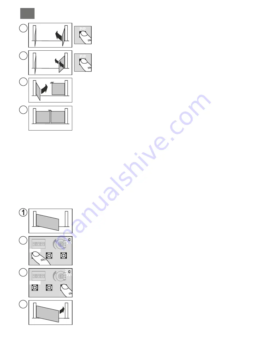
PROGRAMMING ONE SWING-TO GATE, WITHOUT ENCODER CONTROL AND WITHOUT ELECTRICAL
TRAVEL LIMITS
Motor wired to the output M1 and DIP11 set to OFF
In this case the installer will have to manually (using the P/P command) input all the travel limit information. It is also
possible to input the deceleration times at this point (for the final part of the gate movement) or you may try the
default settings by moving dip 9 to ON after programming.
DIP 9 set to OFF during programming:
Deceleration times will not be modified.
DIP 9 set to ON only after programming:
Default deceleration times will be set.
DIP 9 set to ON during programming will oblige you to input ALL the deceleration start values after points:
4a, 4c, 6b and 6d.
Before starting programming check the correct setting and connection of the inputs using the status leds (part. 22,
fig. A):
Leds
BSC, BSA, FT1, FT2, J2 and STP
must b
e ON.
Leds
J1, PC, PA, PED and P/P
must be
OFF.
Switch off the power to the ECU.
Release the motor and move the gate to the position “almost open”.
Re-engage the motor and switch on the power to the installation.
Hold down the PROG button (part. 15, fig. A) for about 3 seconds until led LD1 lights up
(part. 18, fig. A)
The ECU is now in the programming stage.
Press the P/P button (part. 17, fig. A) the gate should begin to close, if it moves in the opening
direction instead, stop programming by switching off the power, invert the wires of the motor
and repeat the procedure from point (1).
If the motor stops before reaching the travel limits increase the torque level using the
trimmer.
2
3b
3a
3c
STOP
STOP
M1
M1
M1
M1
M1
M1
P3
P3
P/P
P/P
LD1
LD1
PROG.
PROG.
When the gate has completely closed, press P/P, the motor will stop and begin to
open automatically.
At this point you may manually insert the DECELERATION start point using
P/P if DIP 9 is set to ON. The motor will stop for a second and then begin to
move again.
When the gate has opened completely (reaching the mechanical stop) press P/P
to stop the motor, pause time memorisation will start (if automatic reclosing is not
being used you may move directly to point (6a).
Once the desired pause time has elapsed, press button P/P and the motor will
begin to close.
At this point you may manually insert the DECELERATION start point using
P/P if DIP 9 is set to ON. The motor will stop for a second and then begin to
move again.
When the gate has completely closed, press P/P, the motor will stop, led LD1 will
switch off and the ECU will quit the programming mode.
Checks: force, times and stopping points. We advise you to consider inserting
deceleration points (DIP 9 set to ON) to reduce impact against the travel limits so
reducing wear and tear on the mechanical parts.
Repeat programming if you have modified the mechanical travel limits.
4a
4b
5
M1
M1
6a
6b
FINE PROG.
PROGRAMMING ONE SWING-TO GATE, WITH ENCODER CONTROL AND WITHOUT ELECTRICAL
TRAVEL LIMITS
The procedure is the same as the previous paragraph but you do not need to press P/P at points 3c, 4b and
6b.
In this case the ECU will AUTOMATICALLY detect all the travel limit information. Programming is more precise and
quicker thanks to the encoder sensor. The deceleration points and times will be inserted automatically. To modify
them you need only insert the new values during programming (DIP9 set to ON).
This procedure allows you to modify the pause time set during a previous programming procedure.
This operation must be carried out with the gate closed.
1) Press the PROG button (part. 15, fig. A) and hold it down until the Led LD1 remains lit (part. 18, fig. A)
2) Press the PROG button again, led LD1 will start to flash and the ECU will begin to memorise the pause time.
3) Once the desired pause time has elapsed, press the PROG button. Led LD1 will switch off and the procedure will terminate.
MODIFYING THE PAUSE TIMES
According to the standard EN 12445 every automation installation must pass the impact test measured with the specific
instrument.
Carry out the impact test and adjust the motor force by rotating the trimmer (part. 21, fig. A).
If this is not sufficient to remain within the boundaries of the graph supplied by the standards in force, we advise you to install a
rubber protective edge at the head of the gate so as to soften the impact.
If you have adjusted the sensitivity setting and added a rubber profile to the head of the gate and you are still unable to satisfy
the standards in force, you will need to add other safety devices such as a sensitive safety edge to the moving part of the gate.
SENSITIVITY ADJUSTMENT
GB
I
GB
2
1
52


