Tektronix WFM2300 How-To Manual Download Page 10

SDI Eye and Jitter Measurements 

How-to Guide 


10


www.tektronix.com/wfm2300


10

How to Configure Eye Measurements 

1.  Select one of the tiles (1, 2, 3 or 4) and press the 

PHY 

button. 

2.  Push and Hold the 

PHY 

button to enable the menu. 

3.  Using the up and down arrows to navigate to 

Display Type 

and press right arrow to select the sub 

menu as shown in Figure 7. 

4.  Use the up and down arrows to select the

 Eye Display

The Eye display provides a visual check on the characteristics of the received SDI signal and a variety 
of information can be determined from the display and the measurement values. 

The following displays can be used to identify common characteristics or problems with the SDI signal. 
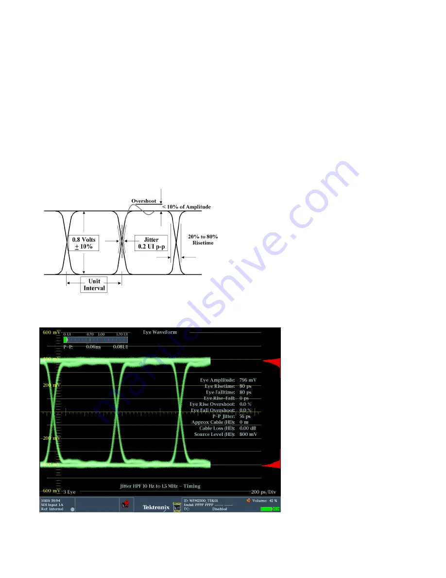
SMPTE standards provide specification for the launch amplitude of an SDI signal output from the device 
Figure 7a. The test signal generator output of the WFM2300 was directly connected to the SDI A input 
and direct measurements were made of the physical layer parameters in Figure 7b. 


Figure 7a. 

Eye Launch Amplitude specifications. 


Figure 7b. 

Generator output connected to SDI A. 

Summary of Contents for WFM2300

Page 1: ...How to Guide SDI Eye and Jitter Measurements WFM2300 Portable Waveform Monitor...

Page 2: ...SDI Signal Path 3 How to Configure Video Session Display 4 How to Configure SDI Status Display 5 Cable Stress Loop 7 How to Configure SDI Stress Loop Amplitude 9 How to Configure Eye Measurements 10...

Page 3: ...al Path Error Free signal path check for CRC HD or 3G or EDH Error Detection Handling if present within SD SDI signals Use the video session of the WFM2300 to determine this Determine if the signal pa...

Page 4: ...or C Chroma samples This is shown in the lower statistics information of Figure 1 If the signal attached to the WFM2300 is error free then the Status will show OK in green If a CRC error occurs then t...

Page 5: ...f cable The SDI status display provides an estimated cable length measurement based on selection of specific cable types NOTE Most manufacturers specify the performance of their equipment to a specifi...

Page 6: ...selected by the user Source Level Shows the calculated launch amplitude of the signal source assuming a continuous run of cable Cable Type Shows the cable type used to make physical layer measurement...

Page 7: ...gnal is producing CRC errors every second or every minute then the signal is marginal and the user needs to investigate further using the eye and jitter displays to determine the problem The cable typ...

Page 8: ...nsmitted SDI signal If the device fails to recover the signal then the stress loop can be removed and the test signal generator output of the WFM2300 can be directly connected to the link to test the...

Page 9: ...interfering signal is set to a frequency of 20MHz and causes varying vertical offset in the eye display This interfering signal is not actually jitter and therefore does not produce time or phase modu...

Page 10: ...visual check on the characteristics of the received SDI signal and a variety of information can be determined from the display and the measurement values The following displays can be used to identify...

Page 11: ...difficult to determine the rise and fall of the transitions although the amplitude and jitter of the signal can be measured Figure 8a Addition of stress loop 20m Belden 1694A Figure 8b Long length of...

Page 12: ...those parts of the trace that occur more frequently A blue color is used for less frequently occurring parts of the trace with cyan green yellow and the red showing increasing frequency of that part...

Page 13: ...arrel connector or problem with a cable or connections Unequal rise and fall time of the transitions causes a shift in the 50 point of the eye display as shown in Figure 10b In this case the rise time...

Page 14: ...ble the menu 3 Using the up and down arrows to navigate to Display Type and press the right arrow to select the sub menu 4 Use the up and down arrows to select the Jitter Display 5 Jitter can be obser...

Page 15: ...itter the value is reduced to 0 05UI In an active device typically more than one frequency of jitter is present within the signal and is a complex addition of various frequency components typically at...

Page 16: ...n SDI device will track changes within a certain range at lower frequencies related to line and field rate At high frequencies it can be more difficult for the PLL to lock to these large changes and t...

Page 17: ...when the 100kHz filter is selected then the PLL may have problems tracking these changes and cause a disturbance to the clock and data that will produce errors in the signal Another instance is if a j...

Page 18: ...s function perform the following operation 1 Select one of the tiles 1 2 3 or 4 and press the PHY button 2 Select either the Eye or Jitter display 3 Press the DISPLAY button to bring up the menu 4 Use...

Page 19: ...in order to represent the typical performance of a video device and to ensure a stable lock to the SDI signal The eye display itself is not bandwidth limited and therefore may show more jitter or wan...

Page 20: ...o see if this interfering signal causes problems for the receiver Alternatively the user can select a pathological test signal to be generated from the WFM2300 to stress the performance of the PLL or...

Page 21: ...7 5000 Russia 7 495 7484900 Singapore 65 6356 3900 South Africa 27 11 206 8360 Spain 00800 2255 4835 Sweden 00800 2255 4835 Switzerland 00800 2255 4835 Taiwan 886 2 2656 6688 United Kingdom 00800 2255...

Reviews: