Maintenance
VX1411 MainFrame Instruction Manual
6–17
Fan 1
Fan 2
Power supply
A1
Power supply
interface
board
J1
J2
Fan control board
(A3)
Backplane board
A4
30
96
P20
P21
AC in
3
3
On / Standby
switch
Fan speed switch
P1
P2
0J4 0P3 0J1
0J2
J23
J22
3
3
J20
J21
J24
0P2
0P1
1P1
2P1
3P1
4P1
5P1
6P1
7P1
8P1
9P1
10P1
11P1
12P1
1P2
2P2
3P2
4P2
5P2
6P2
7P2
8P2
9P2
10P2
11P2
12P2
Slot 0
Slot 1
Slot 2
Slot 3
Slot 4
Slot 5
Slot 6
Slot 7
Slot 8
Slot 9
Slot 10 Slot 11 Slot 12
3
S1 J7 J8
4
4
0J3
0P2
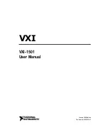
Figure 6–10: Mainframe block diagram
Fan Control Board.
The fan control board (A3) controls the speed of the two fans,
full or low. The fan control board connects directly to the backplane at 0J3 and
0P2.
The two fans connect to the fan control board at J7 (Fan2) and J8 (Fan1). The
Fan Speed switch (S1) selects either low fan speed (LOW) or full speed (FULL).
Artisan Technology Group - Quality Instrumentation ... Guaranteed | (888) 88-SOURCE | www.artisantg.com