


Jumper Settings
TLA 720 Benchtop Chassis and TLA 7XM Expansion Chassis Service Manual
4–25
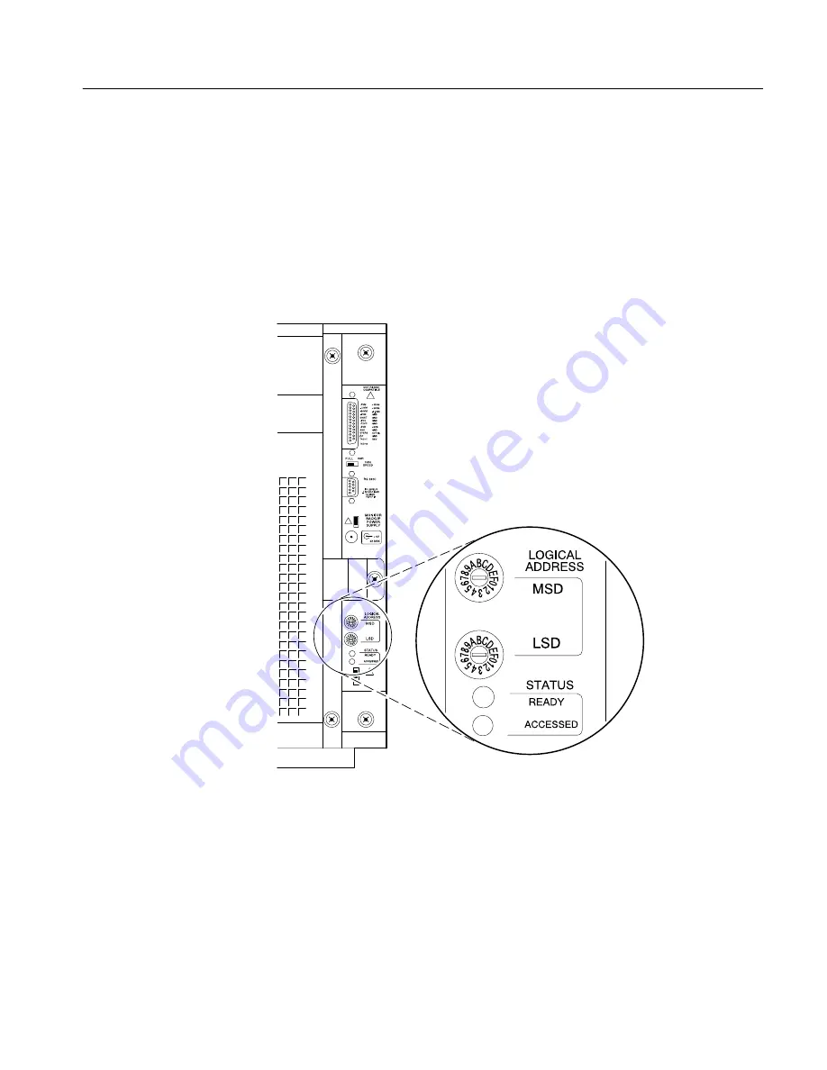
Enhanced Monitor Board Logical Address Switch Settings
You can set the logical address of the mainframe with the switches on the rear
panel. Figure 4–17 shows the locations of the logical address switches on the
rear of the enhanced monitor panel.
If all modules in the mainframe are set to FF, the resource manager will
“dynamically” configure the module’s logical address. If a module is set to a
logical address other than FF, you must be careful to choose a unique address.
Figure 4–17: Logical address switches
Summary of Contents for TLA 720
Page 13: ...Table of Contents viii TLA 720 Benchtop Chassis and TLA 7XM Expansion Chassis Service Manual...
Page 22: ...Specifications...
Page 23: ......
Page 38: ...Operating Information...
Page 39: ......
Page 105: ...Command Groups 2 66 TLA 720 Benchtop Chassis and TLA 7XM Expansion Chassis Service Manual...
Page 111: ...TEST Subsystem 2 72 TLA 720 Benchtop Chassis and TLA 7XM Expansion Chassis Service Manual...
Page 124: ...Theory of Operation...
Page 125: ......
Page 128: ...Maintenance...
Page 129: ......
Page 155: ...Jumper Settings 4 26 TLA 720 Benchtop Chassis and TLA 7XM Expansion Chassis Service Manual...
Page 178: ...Options...
Page 179: ......
Page 182: ...Diagrams...
Page 183: ......
Page 186: ...Replaceable Mechanical Parts...
Page 187: ......
Page 198: ...Replaceable Parts TLA 720 Benchtop Chassis and TLA 7XM Expansion Chassis Service Manual 7 11...
Page 203: ...Replaceable Parts 7 16 TLA 720 Benchtop Chassis and TLA 7XM Expansion Chassis Service Manual...
Page 204: ...Index...
Page 205: ......
Page 211: ...Index Index 6 TLA 720 Benchtop Chassis and TLA 7XM Expansion Chassis Service Manual...
Page 212: ......
Page 213: ......


