


6
define a starting point on when to start drawing the signal on the screen. The
Level
knob in the trigger
menu sets a horizontal line on the oscilloscope where any time the signal voltage goes above that line,
the oscilloscope will start drawing a signal on the screen.
Run / Stop and Single Buttons
Normally you will keep the oscilloscope in the Run mode. The
Run / Stop
button will light up Green to
indicate it is in the run mode. Pressing the
Run / Stop
button turns the button red and freezes the
screen. If you wish to take one single measurement, simply press the
Single
button. Press the
Run /
Stop
button again to turn the run mode back on.
Firmware
Firmware in most test equipment controls the entire device, much like the operating system of a
computer. Firmware is programmed into permanent memory of the device, like an EEPROM. Many
times test equipment manufacturers will update their firmware to fix bug or add new features to a
product. It is important to know the firmware of all your test equipment and keep track of new versions
of firmware for your test equipment. The current version of firmware for the Tektronix TBS1052B-EDU
oscilloscope is v4.06 as of 01/10/2017.
Checking the firmware
1.
Press
Utility
button on the front panel.
2.
Press the
–more- page 1 of 3 softkey
twice to get to page 3 of 3. Then press
System Status
.
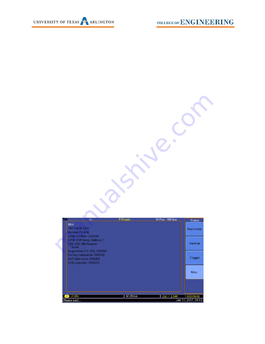
Press
Misc
. to see the firmware, serial number, communication addresses and to see the
status of different tests the scope has undergone.
3.
The firmware is listed and below the model number. See
Figure 6
.
4.
If new firmware is available,
DO NOT INSTALL FIRMWARE YOURSELF
. Contact lab personnel
and we will update the Tektronix oscilloscope for you.
Figure 6


