P77DESKEW Fixture Instructions
Deskew procedure
The deskew function compensates for signal delays that occur between probes
due to different tips or cable lengths. The oscilloscope deskew feature applies
deskew values after it completes each acquisition. The deskew values do not
affect logic triggering.
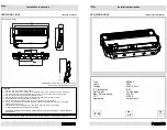
Refer to the following illustration while connecting the probes and cables to the
deskew
fi
xture.
Figure 1: Connection diagram
1.
Connect the deskew
fi
xture to a USB power source, such as the front panel
USB connector on the oscilloscope. The LEDs on the
fi
xture will turn on.
2.
Connect the probes to oscilloscope channels where they will be used.
3.
Connect the TekFlex tips to the ends of the main probe cables.
4.
For single-ended inputs, connect an SMA cable from a single source, such as
the FAST EDGE output connector on the oscilloscope to the A input of the
fi
xture.
5.
If using a signal generator with differential inputs, connect the + output of
the signal generator to the A input of the
fi
xture using an SMA cable. Then
connect the - output of the signal generator to the B input of the
fi
xture using
an SMA-style cable with equal electrical length as the
fi
rst SMA cable.
NOTE.
If you are deskewing probes with solder tips, try to use the same solder
tips with the deskew
fi
xture that you will use to take measurements. If that is not
possible, try to use a solder tip of similar length to the one you have soldered to
your device.
2
P77DESKEW Fixture Instructions