Model 6517B Electrometer User's Manual
Section 3: Connections
6517B-900-01 Rev. B August 2022
3-3
Figure 10: Maximum input levels
Input protection
The 6517B incorporates protection circuitry against nominal overload conditions. However, a high
voltage (>250 V) and resultant current surge could damage the input circuitry. A typical test circuit to
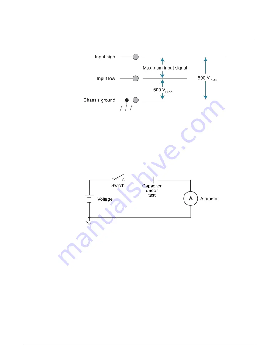
measure the leakage current of a capacitor is shown below. When the switch is closed, an initial
surge of charging current flows and the high voltage is seen across the input of the 6517B.
Figure 11: Capacitor test circuit without protection
Adding a resistor and two diodes (1N3595), as shown in the following figure, provides considerable
extra protection. The resistor must be large enough to limit the current through the diodes to 10 mA or
less. It must also be large enough to withstand the supply voltage. The protection circuit should be
enclosed in a light-tight conductive shield.
This protection circuit is also useful when measuring the insulation resistance of films or high-voltage
cables. Without the added protection, a pinhole or other defect could cause an arc, damaging the
6517B input.


