


Circuit Description—485/R485 Service
5 ohms. Line current charging C1822 and C1823 is limited
by the thermistors. As the instrument continues to operate,
the thermistors heat and drop in resistance. When the
instrument is turned o ff, the Line Stop circuit stops the
Inverter, leaving C l822 and C l823 charged. The line
storage capacitors now discharge through R1822 and
R1823 at a rate approximately equal to the thermal
recovery of the thermistors. This rate ensures enough
thermistor resistance to lim it surge current whenever the
instrument is turned back on.
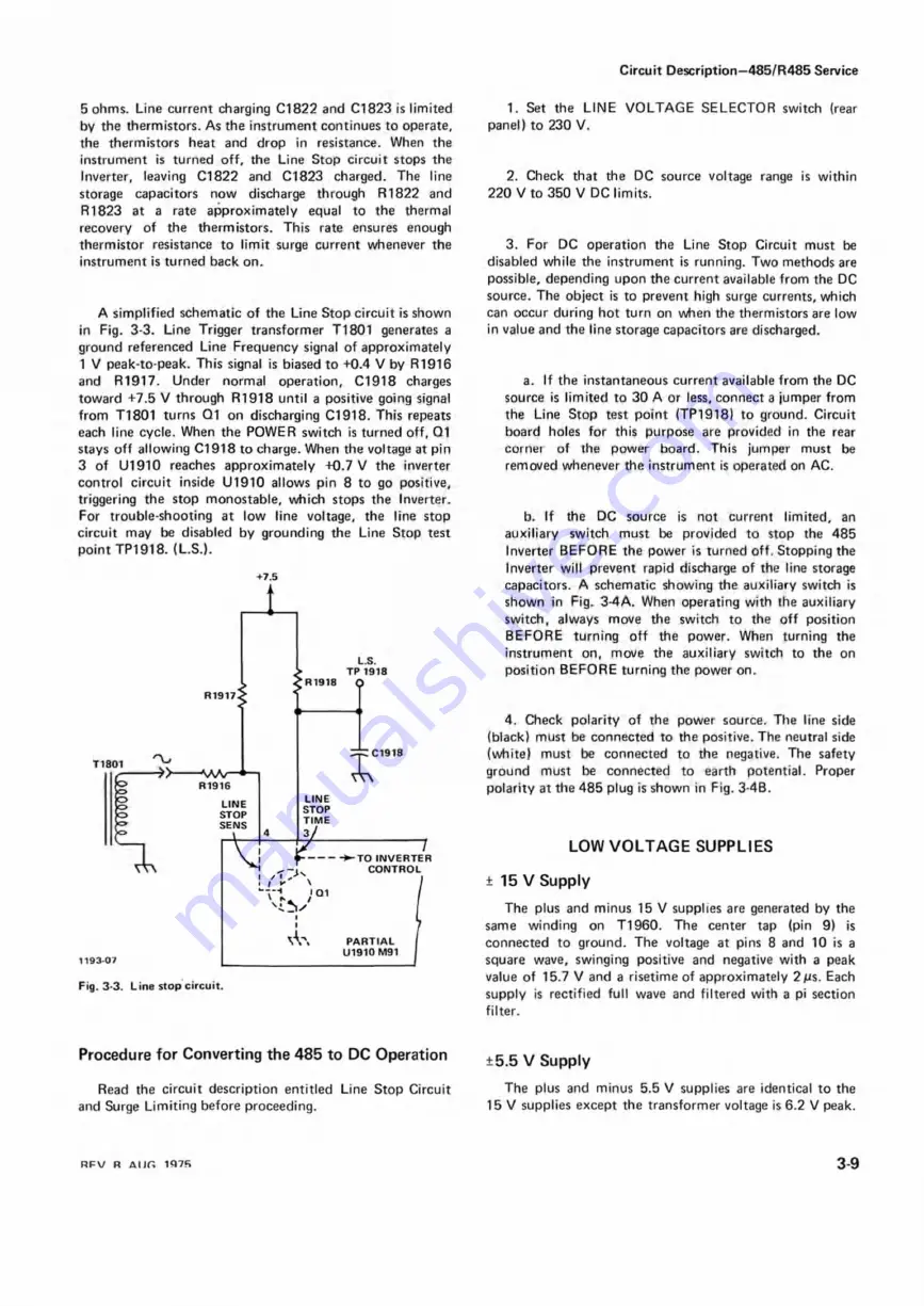
A simplified schematic of the Line Stop circuit is shown
in Fig. 3-3. Line Trigger transformer T1801 generates a
ground referenced Line Frequency signal of approximately
1 V peak-to-peak. This signal is biased to +0.4 V by R1916
and R1917. Under normal operation, C1918 charges
toward +7.5 V through R1918 until a positive going signal
from T1801 turns Q1 on discharging C1918. This repeats
each line cycle. When the POWER switch is turned off, Q1
stays o ff allowing C l918 to charge. When the voltage at pin
3 of U1910 reaches approximately +0.7 V the inverter
control circuit inside U1910 allows pin 8 to go positive,
triggering the stop monostable, which stops the Inverter.
For trouble-shooting at low line voltage, the line stop
circuit may be disabled by grounding the Line Stop test
point TP1918. (L.S.).
+7.5
1
1193-07
L.S.
TP 1918
R 1918
Q
R1917<
-AAA/— —
R 1916
LINE
STOP
SENS
:C1918
LINE
STOP
TIME
3>
r
I
I
I
vV\
I 01
-TO INVERTER
CONTROL
PARTIAL
U1910 M91
Fig. 3-3. Line stop circuit.
1. Set the LINE VOLTAGE SELECTOR switch (rear
panel) to 230 V.
2. Check that the DC source voltage range is within
220 V to 350 V DC limits.
3. For DC operation the Line Stop Circuit must be
disabled while the instrument is running. Two methods are
possible, depending upon the current available from the DC
source. The object is to prevent high surge currents, which
can occur during hot turn on when the thermistors are low
in value and the line storage capacitors are discharged.
a. If the instantaneous current available from the DC
source is limited to 30 A or less, connect a jumper from
the Line Stop test point (TP1918) to ground. Circuit
board holes for this purpose are provided in the rear
corner of the power board. This jumper must be
removed whenever the instrument is operated on AC.
b. If the DC source is not current limited, an
auxiliary switch must be provided to stop the 485
Inverter BEFORE the power is turned off. Stopping the
Inverter will prevent rapid discharge of the line storage
capacitors. A schematic showing the auxiliary switch is
shown in Fig. 3-4A. When operating with the auxiliary
switch, always move the switch to the o ff position
BEFORE turning o ff the power. When turning the
instrument on, move the auxiliary switch to the on
position BEFORE turning the power on.
4. Check polarity of the power source. The line side
(black) must be connected to the positive. The neutral side
(white) must be connected to the negative. The safety
ground must be connected to earth potential. Proper
polarity at the 485 plug is shown in Fig. 3-4B.
LOW V O L T A G E SUPPLIES
± 15 V Supply
The plus and minus 15 V supplies are generated by the
same winding on T1960. The center tap (pin 9) is
connected to ground. The voltage at pins 8 and 10 is a
square wave, swinging positive and negative with a peak
value of 15.7 V and a risetime of approximately 2ps. Each
supply is rectified full wave and filtered with a pi section
filter.
Procedure for Converting the 485 to DC Operation
Read the circuit description entitled Line Stop Circuit
and Surge Limiting before proceeding.
±5.5 V Supply
The plus and minus 5.5 V supplies are identical to the
15 V supplies except the transformer voltage is 6.2 V peak.
R F V R A im 1<J7R
3-9
Summary of Contents for 485
Page 3: ...485 R485 rviice T h 5 0 Oscil oscope ...
Page 74: ...Rackmounting 485 R485 Service 6 6 ...
Page 128: ...485 R485 Service MAR 1979 5 m V B A L ADJ ...
Page 152: ... 0 iT s i ...
Page 164: ...2S2 n eKn s e s 5 4 85 Os c illo sc o p e REV F A U S 1 9 7 7 I 1 9 3 5B POWER SUPPLY 773 ...
Page 178: ......
Page 179: ...485 R485 OSCILLOSCOPE REV D MAR 1977 ...
Page 184: ...REV C MAR 1976 485 R485 OSCILLOSCOPE ...
Page 197: ......


