


Instruction Manual
Tek-DP 1650A
www.tek-trol.com
Technology Solutions
12
3.1.7
TYPE FTL-73, FTL-75 & FTL-76 FLUID BAR
3.2
Installation Procedure
1.
Verify that the line pressure & temperature are within the rated limits for respective models.
2.
Grind off paint or other coatings from the pipe in the area where the Flow-Tap is to be
installed. (Except for steam applications, Flow-Tap may be installed at any angle around the
pipe.)
3.
Drill or bum a 35.0 mm diameter hole in the pipe &for Type FTM-76 & FrH-76 drill or burn. a
35.0 rim diameter hole on the opposite side of the pipe for end support.
4.
Tack weld the 40 NB weld coupling to the pipe. The coupling must be aligned perpendicular to
the pipe axis & square to its plane. For Type FTM-76 & FTH-76, tack weld the end support on
the opposite side of the weld coupling. Ensure the end support is aligned perpendicular to the
pipe axis & in line with the weld coupling.
5.
Install the Flow-Tap unit-isolating valve on the process connection. Verify that the valve is in
the fully open position, & that the stem is in line with the pipe to ensure clearance for the
insert-retract rods.
6.
Install the Flow-T ap cage nipple into the unit-isolating valve.
7.
Inspect Flow-Tap assembly to ensure that the insert-retract mechanism is fully retracted.
8.
Install the Flow-Tap assembly on the cage nipple. When tight, the flow arrow on the top of the
Flow-Tap head must point in the direction of flow.
9.
Initiate sensor insertion by rotating the drive nuts clockwise as viewed from the top, using the
ratchet wrench supplied with the unit. The nuts must be tightened alternately, about two
turns at a time to prevent binding resulting from unequal loading. Continue this procedure
until the sensor contacts the opposite side of the pipe or end support.
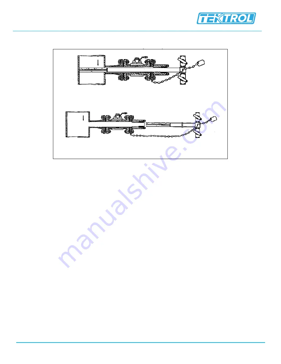
Fully inserted
Fully retractable
Fig 12: Type FTL-73, FTL-75 & FTL-76 Fluid Bar


