2 • IL573 Tek-ENTRY
®
Telephone Entry System Phone-Line Version Manual
Copyright © TekTone Sound & Signal Mfg., Inc. All Rights Reserved.
Installation Tips
1. Make arrangements with the telephone company to install a telephone line for use by
the system. Install the telephone line jack inside the entry panel enclosure. When
ordering, specify the equipment DOC approval number (1949 5264 A).
2. One 16 volt/20 VA UL
®
Listed and CSA approved class 2 power transformer is
required for system operation. A second transformer is required for door strike
activation. This transformer should have the necessary voltage and current rating for
the door strike that is to be used (max. 28 volts, 3 amps).
3. Transformers and remote devices such as the door strike, fire alarm and door contacts
must be wired to the system controller located in the enclosure housing. A wiring
channel at the rear of the system enclosure must be provided for these devices. Follow
local building code requirements for low voltage wiring.
4. If a postal service lock is to be installed, make arrangements with the local post office
to supply the lock.
5. In multiple entrance applications, two additional wires are required from each entry
system to interconnect the system controllers. A telephone line extension jack must
also be installed at each entry location (see
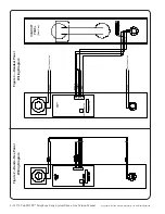
Figure 1—System Wiring Diagram
).
6. Do not mount the entry panel in an area where it may be exposed to near-horizontal
water or moisture sources, for example driving rain or water spray.
System Installation Step by Step
Refer to
Figure 1—System Wiring Diagram
for terminal locations. Also refer to
Figure 2—
Hands-Free Panel Wiring Diagram
and
Figure 3—Handset Panel Wiring Diagram
.
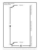
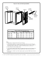
1. Mount the system enclosure to the wall in the location closest to the building’s
controlled entry point. (Refer to
Figure 5—Frame and Housing Installation
.)
2. Connect the door strike wires to terminals “D1” and “D2” if DC (silent) operation is
desired, or to terminals “D3” and “D4” for AC (buzzing) operation. The maximum
switched door strike load is 28 volts at 3 amps.
3. An auxiliary switched device (such as a parking gate) may be controlled through the
auxiliary relay contact that is available by connecting to terminals “NC” (normally
closed), “C” (common), and “NO” (normally open). The maximum switched auxiliary
load is 28 volts at 3 amps. This contact will change to the energized state for one second
when the tenant dials “6” from their DTMF (touchtone) telephone.
4. Terminal “PL” is for the postal service lock. Closing of a normally open switch
between terminals “PL”and “G” is required for activation. The system is pre-wired for
this service, but requires a lock to be installed on the rear of the system control panel
(optional on TE905A). Remove the panel plug button for the postman’s key and
remove the retaining strap on the switch actuator. Mount the lock with the supplied
hardware. Adjust the switch actuator for proper operation with the lock.
5. Terminal “TC” is for connection of a door timer cut-off contact. A normally open
contact that closes when the door has been opened will cut-off the door timer and
instantly re-lock the door. This is used to prevent tailgating of unwanted visitors
through the entry doors. Connect between terminals “TC” and “G.”
6. Terminal “FA” is for connection to the building fire alarm system. A normally open
alarm contact that closes during an alarm condition can be connected between
terminals “FA” and “G” to pulse open the entry door during a fire or other emergency.
System Installation and Programming –——————————


