


TTM 01-G Manual / October 2018
16
Factory Hardware Options
Power Supply Options
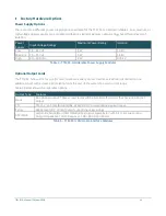
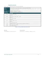
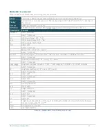
There are three different power supply options available for the TTM 01-G, detailed in Table 4. Low, medium, or
high voltage power supplies are available and feature similar maximum output ratings but different levels of
isolation.
Power
Supply
Input Voltage Ratings
Maximum Power Rating
Isolation
Low
14 – 36 Vdc.
4 W
1.6 kV
Medium 20 – 75 Vdc.
4 W
1.6 kV
High
90 – 300 Vdc.
4 W
3.75 kV
Table 4 - TTM 01-G Orderable Power Supply Modules
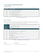
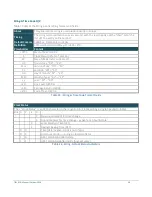
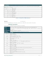
Optional Output Cards
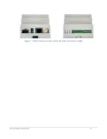
The TTM 01-G has a slot for one I/O card, to allow a variety of user interfaces. Each card is limited to one
additional port with at least 3 kV isolation from the rest of the system to avoid current loops.
Table 5 below shows the orderable options:
Output Type
Features
None
No optional output. These screw clamps will be blanked off on units that have no optional
output.
TTL
TTL (5 V, 150 mA) IRIG-B (B00x, B22x), DCF77 or user defined pulse output.
Serial
RS232 level (9 V, 10 mA) output supporting serial strings.
AM IRIG-B
Amplitude Modulated (AM) IRIG-B (B12x) signal, typically 8 V with 3:1 mark space ratio.
Output Impedance 120 Ω. Requires
a 100 –
180 Ω terminator.
Table 5 - TTM 01-G Orderable Interface Modules
Summary of Contents for TTM 01-G
Page 1: ...TTM 01 G USERMANUAL ...