


TTM 01-G Manual / October 2018
13
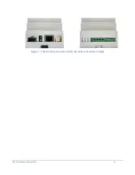
Mounting the TTM 01-G
The TTM 01-G is designed to be mounted to a standard 'Top Hat' din rail mount using the supplied clips on the
base (see Figure 6). The clips can also be used to screw mount the unit by extending them beyond the case
edge.
Connecting the TTM 01-G
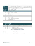
The TTM 01-G has an SMA connector, RJ-45 / 100Base FX connector and ST Fiber output on the top, and a row
of rising clamp screw terminals on the bottom. Any connection not required may be left unterminated. The
screw terminals are designed for the following cables:
• 0.2 - 4.0mm² (30 – 12 AWG) solid cable
• 0.2 - 2.5mm² (30 - 14 AWG) stranded cable
The SMA
(ANT)
connector should be connected to the antenna lead-in cable. Care should be used to ensure that
the cable bend radius is kept within the cable specification and the SMA connector is not placed under strain.
The Fiber TTM 01-G can be connected to an ST multimode Fiber cable for Ethernet and is labeled
ETH
on the
case whereas the IRIG-B fiber out is simply labeled
TX
.
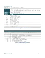
The connections from left to right along the bottom are:
•
Optional output (
OPT
) ‘-’ and ‘+’
•
Alarm (
ALM
) ‘-’ and ‘+’
•
TTL ‘-’ and ‘+’
•
Ground
•
Power Supply Negative
•
Power Supply Positive
If the optional output isn’t fitted, then the unused terminals are covered.
Figure 6 - Base of TTM 01-G
Summary of Contents for TTM 01-G
Page 1: ...TTM 01 G USERMANUAL ...