


TTM 01-G Manual / October 2018
12
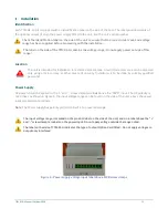
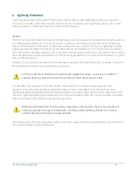
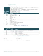
Hazardous Voltage
Figure 4 - PWR and ALM screw clamp terminals
Up to 300 V may be present at the power input port “PWR”. Up to 275 V may be present at the alarm
relay port “ALM” (in Figure 4). These voltages are supplied to the unit only, and not generated by the
unit. However, the installer must exercise care in wiring the screw clamps to ensure bare copper is
not accessible.
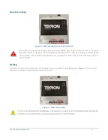
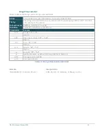
Earthing
The GND connection is located next to the power supply input terminals (highlighted in
). This must be
connected to earth for full protection of the TTM 01-G.
Figure 5 - GND screw clamp
The unit must be safety earthed whenever it is powered on, using the earth terminal as pictured in
The cable cross section must be equal to or greater than 0.2 mm
2
(30 AWG).
Summary of Contents for TTM 01-G
Page 1: ...TTM 01 G USERMANUAL ...