Installing Devices 6-8
6.6.2
COM2 (J4)
The Serial Port COM2 supports both RS-232 and RS-485 standard via J4 connector
(standard male DB9 connector at the edge of the board).
COM2 pinouts (RS-232 and RS-485) are given in Appendix E
- Board Connectors and
Pinout
.
When configured for RS-485 the TEK-AT4L
PLUS
supports either full-duplex or party line
communication.
Full Duplex Operation
Upon power-up or reset, the RS-485 interface circuits are automatically
configured for full duplex operation. J4(3,4) act as the receiver lines and J4(5,6)
as the transmitter lines.
Party Line Operation
In order to enable party line operation, the user must first write "1" to bit 3 at I/O
address 201h. This allows the transceiver (J4 3,4) to be controlled by the RTS
signal. Upon power-up or reset, the transceiver is by default in "receiver mode"
in order to prevent unwanted perturbation on the line.
In party line operation, termination resistors R9 and R10 must be installed only
on the boards at both ends of the network.
6.7 Parallel Printer Port Connector
(J7)
The Parallel Printer Port (J7) provides the necessary control signals for Centronics-
compatible parallel interface. The connection is done through a standard female DB25
connector located at the edge of the board. Its pinout is given in Appendix E
- Board
Connectors and Pinout
.
The port is set to output 8-bit data by default. It can be changed to input data simply by
writing 10h to address 201h (set bit 4).
WARNING:
Port 201h is also used to control the Watchdog Timer. Therefore, it is
highly recommended you keep a mirror image of port 201h in memory
Summary of Contents for TEK-AT4L Plus
Page 7: ...PRODUCT DESCRIPTION 1 PRODUCT OVERVIEW 2 ONBOARD SUBSYSTEMS...
Page 9: ...Product Overview 1 2 TEK AT4LPLUS Block Diagram...
Page 26: ...Installing Devices 6 3 CONNECTOR LOCATION...
Page 35: ...Setting Jumpers 8 3 JUMPER LOCATIONS...
Page 36: ...Setting Jumpers 8 5 TABLE 8 1 Jumper Settings W1 W11...
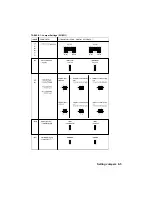
Page 37: ...Setting Jumpers 8 6 TABLE 8 2 Jumper Settings W12 W19 W26...
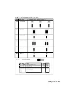
Page 38: ...Setting Jumpers 8 7 TABLE 8 3 Jumper Settings W20 W25 SW1 SW2...
Page 41: ...APPENDICES A PRODUCT SPECIFICATIONS B BOARD DIAGRAMS C CONNECTOR PINOUTS...
Page 43: ...Board Diagrams B 1 B 1 TEK AT4LPLUS Assembly Diagram Top View...
Page 44: ...Board Diagrams B 3 B 2 TEK AT4LPLUS Mounting Holes...
Page 45: ...Board Diagrams B 5 B 3 TEK AT4LPLUS Mechanical Specifications...


