Customizing The Board 5-9
If a hardware or software failure occurs such that the Watchdog is not refreshed, a reset
pulse is generated by the Watchdog to restart the processor.
WARNING
: The user program must provide the first access to address 201h, and
must also include the refresh routine. In addition, be certain to keep a
mirror image of register 201h when programming it. This is necessary
since register 201h is a write-only user register and, as a result, is not
used by the BIOS.
TABLE 5-5:
Watchdog Timer Register
ADDRESS
REGISTER
201 bit 0
read/write
Watchdog enable
201 bit 1
read/write
Watchdog refresh
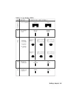
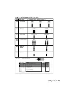
Jumper W12 must be installed to enable activation of the Watchdog. If jumper W12 is
removed, the Watchdog is disabled.
5.9.3
Power Failure Detector (PFD)
The PFD, which generates a non-maskable interrupt (NMI) when a failure occurs,
provides a 1.25V threshold for DC power fail warning, low battery detection W7(2-3), or
when monitoring a power supply other than +5VDC W7(1-2). The Power Detection
Output (PDO) of the power failure detection circuit is connected to IOCHECK (NMI).
Jumper W13 allows the user to disable this feature. However, the PDO status is still
available by reading I/O address 201h bit 3.
The detection circuit generates a non-maskable interrupt when a power failure occurs.
The status of the PDO is available at I/O address 201h bit D3. For example, if it reads 0,
the circuit has detected a low power warning from the power detect pin on 6, connector
J5.
Pin 6 on connector J5 is used for the power detection input. This input can only accept
DC voltage. The line is monitored via two user-defined external resistors, R19 and R18,
which are connected to the power failure input (Note: R19 is a surface mount resistor and
R18 is fixed to 1KB). The user should position the resistors according to the monitoring
level desired. If the voltage level supplied to this line drops below 1.3V typical, a
Power
Fail
status is detected and directed to the NMI line.
Summary of Contents for TEK-AT4L Plus
Page 7: ...PRODUCT DESCRIPTION 1 PRODUCT OVERVIEW 2 ONBOARD SUBSYSTEMS...
Page 9: ...Product Overview 1 2 TEK AT4LPLUS Block Diagram...
Page 26: ...Installing Devices 6 3 CONNECTOR LOCATION...
Page 35: ...Setting Jumpers 8 3 JUMPER LOCATIONS...
Page 36: ...Setting Jumpers 8 5 TABLE 8 1 Jumper Settings W1 W11...
Page 37: ...Setting Jumpers 8 6 TABLE 8 2 Jumper Settings W12 W19 W26...
Page 38: ...Setting Jumpers 8 7 TABLE 8 3 Jumper Settings W20 W25 SW1 SW2...
Page 41: ...APPENDICES A PRODUCT SPECIFICATIONS B BOARD DIAGRAMS C CONNECTOR PINOUTS...
Page 43: ...Board Diagrams B 1 B 1 TEK AT4LPLUS Assembly Diagram Top View...
Page 44: ...Board Diagrams B 3 B 2 TEK AT4LPLUS Mounting Holes...
Page 45: ...Board Diagrams B 5 B 3 TEK AT4LPLUS Mechanical Specifications...


