Installing Devices 6-7
6.5 Multi-Function Connector (J3)
The TEK-AT4L
PLUS
offers a 16-pin header to support keyboard, speaker, Reset button,
and LED devices. To output the signals, the cable must be built as follows:
Note
: This cable is available from TEKNOR - referenced as 150-018.
Devices are described as follows:
Speaker
an 8 ohm speaker can be directly connected to pins 7 and 8. All
necessary drivers are installed.
Reset
a Normally Open Push button can be connected to reset the TEK733
(electrical short between pin 13 and 14).
Hard Disk LED
the onboard IDE interface drives an external LED during the drive
activity. Anode must be connected to pin 16. No external current
limiting resistor is required since one is already present.
6.6 Serial Port #2 Connector
(J4)
The TEK-AT4L
PLUS
features two UARTs which are functionally equivalent to the
NS16450. Both are configured as DTE.
6.6.1
COM1(J6)
The COM1 port is buffered directly on the board for RS-232 operations. COM1 is 100%
compatible with the IBM-AT serial port.
Note
: This cable is available from TEKNOR - referenced as 150-019.
Summary of Contents for TEK-AT4L Plus
Page 7: ...PRODUCT DESCRIPTION 1 PRODUCT OVERVIEW 2 ONBOARD SUBSYSTEMS...
Page 9: ...Product Overview 1 2 TEK AT4LPLUS Block Diagram...
Page 26: ...Installing Devices 6 3 CONNECTOR LOCATION...
Page 35: ...Setting Jumpers 8 3 JUMPER LOCATIONS...
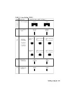
Page 36: ...Setting Jumpers 8 5 TABLE 8 1 Jumper Settings W1 W11...
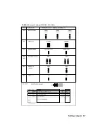
Page 37: ...Setting Jumpers 8 6 TABLE 8 2 Jumper Settings W12 W19 W26...
Page 38: ...Setting Jumpers 8 7 TABLE 8 3 Jumper Settings W20 W25 SW1 SW2...
Page 41: ...APPENDICES A PRODUCT SPECIFICATIONS B BOARD DIAGRAMS C CONNECTOR PINOUTS...
Page 43: ...Board Diagrams B 1 B 1 TEK AT4LPLUS Assembly Diagram Top View...
Page 44: ...Board Diagrams B 3 B 2 TEK AT4LPLUS Mounting Holes...
Page 45: ...Board Diagrams B 5 B 3 TEK AT4LPLUS Mechanical Specifications...


