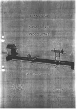
background image

Preliminary Manual 

90-9404-003 

Page 

CONNECTING 

WOODLATHE T O  POWER SOURCE 

If 

the motor is not provided with  a lead and  male plug, this must be wired in by  a 

registered electrician. 

NEW 

The 

woodlathe is supplied 

to 

all markets without a motor, switch or wiring. 

The motor,  switch and wiring leads are supplied as kits separately 

from 

suppliers 

in 

Canada and the 

USA. 

Canada:  The motor with  switch mounted 

on 

it can be supplied. 

In New 

motors 

can 

be supplied with switches. 

Please enquire with 

your 

stockist. 

PLEASE FOLLOW 

MANUFACTURERS 

SAFETY 

INSTALLATION INSTRUCTIONS 

GROUNDING INSTRUCTIONS 

THE MOTOR,  SWITCH 

MUST BE GROUNDED 

WHILE 

I N  

USE TO PROTECT 

THE 

OPERATOR FROM ELECTRIC SHOCK 

If 

there is a malfunction or breakdown, grounding in the electical circuit provides a 

path 

of 

least resistance for electric current to reduce the risk 

of 

electric shock. 

Check that 

the 

leads and wiring used 

with the motor and  switch wirin  have a 

grounding conductor and have a grounding 

lug.  The plug  must be p 

into a 

matching outlet that is properly installed an  grounded in accordance 

all local 

codes and ordinances. 
Have a  certified electrician check the electrical circuit and plugs if the grounding 
instructions are not completely understood 

or 

if 

doubt 

as 

to whether the machine 

or 

is properly  grounded. 

Improper connection 

of 

the equipment grounding conductor can 

in 

the risk of 

an 

electric shock. The conductor 

insulation with an outer surface that is green, 

with or without yellow stripes is the equipment 

conductor. 

If 

repair 

o r  

replacement 

of 

the 

cord 

is 

connect the equipment grounding 

conductor 

t o  

a live terminal. 

DO NOT 

MODIFY 

THE 

PLUG PROVIDED 

WITH 

MOTOR 

SWITCH 

IF IT 

WILL NOT 

FIT THE 

OUTLET HAVE 

THE 

PROPER OUTLET 

'INSTALLED 

BY 

A QUALIFIED ELECTRICIAN. 

Summary of Contents for NOVA TL1200

Page 1: ......

Page 2: ...No loose clothing gloves neckties rings bracelets or other jewellery to get caught in moving parts Nonslip footwear is recommended Wear protective hair covering to contain long hair 12 AbWAYS V S E SAFETY GLASSES Wear safety glasses must comply with ANSI 287 1 Everyday eye glasses only have impact resistant lenses they are not safetyglasses Also use face or dust mask if cutting operation is dusty ...

Page 3: ...hat appropriate size faceplate is used to properly support workpiece workpiece as possible before engaging power 17 WHEN faceplate turning MAKE SURE the screw fasteners do not interfere with the turning tool at the finished dimension of the workpiece 18 ROUGH CUT workpiece as close as possible to finished shape before installing on faceplate 19 TIGHTEN all clamp handles before operating 20 EXAMINE...

Page 4: ...th basic setup instructionsto enableyou to beginturning If you have any queries aboutthe setup or operationplease don t hesitate to contactthe manufacturers At Teknatool we value contact with our customers who are using our products If you have any suggestions or comments about our products we would greatly appreciate hearing from you WARNING SOURCE UNTIL THE LATHE IS COMPLETELY ASSEMBLED AND YOU ...

Page 5: ...lt B e Circlip on Motor Mount Shaft B f Fastenings and Washers to fix motor to Motor Mount Plate C Other Parts 8 s eed Motor Pulley with 5 8 bore C i 4mm Allen Wrench to adjust 8mm grubscrew A 7 j 2MT Live Centre C k 2MT Spur Centre C 1 Polyvee Drive Belt Type 508 56 C A Part of Motor Mount Fastening Kit in accessory box B Part of Motor h4ount Arm Lock Arm Kit C Included in accessory box All these...

Page 6: ...ing at motor from shaft side to ensure lathe spindle turns in an anti clockwise direction looking face on to lathe spindle To chan e to correct rotation Refer Motor instructions or have wiring changed by qualifiefelectrician MOUNTING PULLEY ON MOTOR SHAFT First check the motor shaft size carefully There is only 2 3 thousands of an inch between imperial and metric sizes BUT the difference is enough...

Page 7: ...k of the headstock The assembly of this unit is described on page 6 of this manual Please refer to photo 3 page 5 The motor is locked in position and the belt tensioned when the handle is pb lled towards the operator 1 Push handle away from headstock to release tension 2 Open front cover 3 Support motor weight with your left hand while positioning belt to required pulley step wlth your right hand ...

Page 8: ... _ TL1200 Preliminary Manual 90 9404 003 Page 5 2 3 IVhen the motor is swung up to change belts the motor pulley should be slightly clear of the headstock pulley ...

Page 9: ...e sure it is seated properly 7 Tighten nut up one quarter turn with spanner leadstock to position the toolslide rest late is square across the beds Securing plate must be square to beds CPNDLE NDEX The TL1200 is equipped with a 24 division spindle index The index unit is located above the spindle housin Sight hole for the index numbers is located to the eft of the spindle index To engaoe spindle i...

Page 10: ...path of least resistance for electric current to reduce the risk of electric shock Check that the leads and wiring used with the motor and switch wirin have a grounding conductor and have a grounding lug The plug must be p ugwed into a matching outlet that is properly installed an grounded in accordance wit6 all local codes and ordinances Have a certified electrician check the electrical circuit a...

Page 11: ...ever you use to apply release MAKE SURE THE MOTOR HAS A FOOT MOUNTING AND A FRAME SIZE B56 NZ AUSTRALIA U K NEMA 56 USA CANADA Stage 2 7 Mount motor pulley on motor shaft and fix in place by means of the 8mm grubscrew I provided Use 4mm wrench provided to tighten Stage 3 8 Loosely bolt motor to plate using the M8x25 bolts M8 nuts and M8 washers Yl Use a straight edge butted against one of the head...

Page 12: ...e workshop LATHE HEIGHT FROM FLOOR The height of the lathe from floor is determined by the hei ht of turners that use the lathe Ideally the lathe should be positioned such that tae centre line through the lathe spindle to centre of tailstock spindle is at the same height as the turner s forearm bent so that it is at a relaxed position arallel to the floor If there are several ersons which may be u...

Page 13: ... bowl blank will clear the top rails and legs when it is swivelled through 90 for larger turnings j Step 9 Bolt the bench top to the top rails There are many variations and alterations that could be rnade but so long as the basic sheet bracing effect is retained a strong rigid bench should result Finally the area of the side panel between the legs could make a convenient place to rack chisels face...

Page 14: ...ould further reduce the cost MATERIALS LIST 1 Sheet of 2 4mx1 2mx18mm medium density fibreboard MDF or Customwood This is for the side panels and the base of the box 4 Piecesof 1 6mx100mmx50mm Radiatapine or similar These makethe top and bottom rails 4 Pieces ofmk100rnm Radiata pine or similar These make the legs the length will vary dependlag on what height you make your stand but you will need a...

Reviews: