


32
128-1019-004
Firmware Update
The HMI software plays an important role in the control and functionality of the NOVA Orion lathe. The
firmware loaded onto the HMI panel is responsible of controlling the features and performance of the lathe.
The firmware version of the HMI can be upgraded via the included USB cable accessory and a PC with
internet access. Be sure to check
https://www.teknatool.com/upgrade-your-firmware/
upgrades for your machine, which may allow new features or software improvements that could enhance the
performance of the lathe.
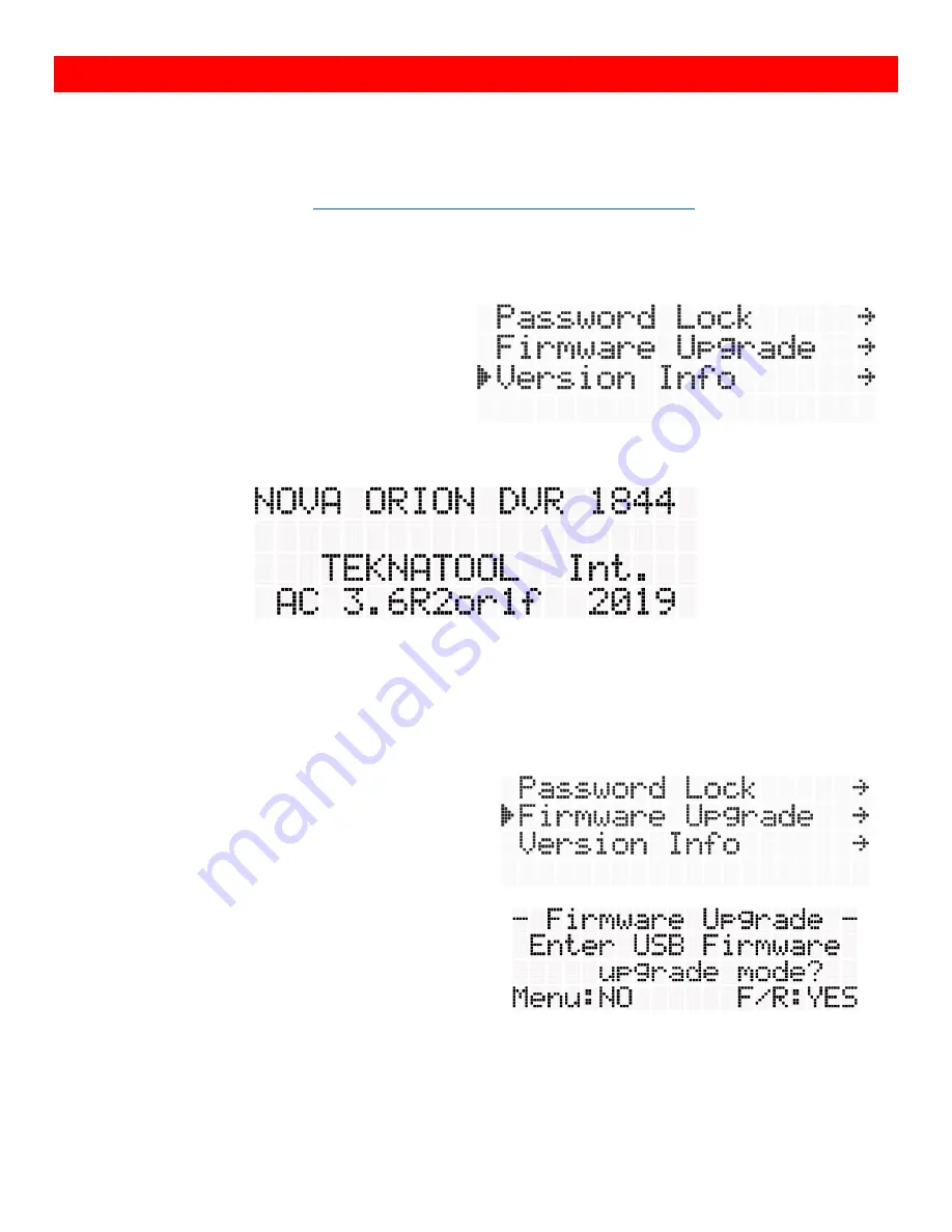
Checking the Firmware Version
The firmware version of the lathe can be checked
from the “Version Info” function located on the last
line of the lathe menu.
The lathe version information will be shown in the screen shown below:
The last line indicates the firmware version of both HMI and main controller.
USB Mode
USB mode is used to perform the firmware update on the lathe HMI.
USB mode is activated by navigating down to the
“Firmware Upgrade”
function on the lathe menu.
Press
<F/R>
to continue into entering USB mode.
Return to the menu screen by pressing
<Menu>