background image

© 2013 

 400_D - 09/13

18 of 32

Item Field

Range

Access

Description

Set to

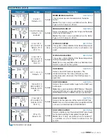
ADJUST

60 to 200°F

(15.5 to 93.5°C)

Default = 180°F

(82.0°C)

Installer

SETPOINT 

SECTION D

The minimum boiler target temperature when a 
Setpoint Call is present. 

ADJUST

°F or °C

Default = °F

Installer

User

UNITS

Selects units for temperature display.

Adjust Menu (3 of 3)

AD

J

U

S

T

 M

E

N

U

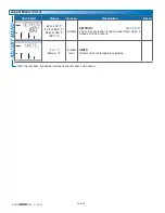
 After the last item, the control returns to the first item in the menu.

Summary of Contents for tN2 house control 400

Page 1: ...tion It can be used in applications ranging from a single zone of baseboard with an on off boiler to multiple radiant floor zones with a modulating condensing boiler This control regulates one space h...

Page 2: ...tallers responsibility to ensure that this control is safely installed according to all applicable codes and standards Improper installation and operation of this control could result in damage to the...

Page 3: ...te toutes les exigences du R glement sur le mat riel brouilleur du Canada Radio Frequency Interference Preparation Tools Required tekmar or jeweller screwdriver Phillips head screwdriver Needle nose P...

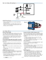
Page 4: ...if applicable Setpoint Device if applicable Pull three conductor 18 AWG LVT cable for the following equipment tekmarNet 4 Accessories User Switch Timer and Wiring Center Low Voltage Wiring Rough In Wi...

Page 5: ...e L N Figure 3 Connect Line Voltage Hot Strip wires 1 2 inch 13 mm Installed wires are not removable 12 18 AWG DHW Pump Pump Power L 400 Boil System Pump DHW Pump Power Source L N Boil System Pump Fig...

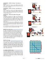
Page 6: ...fasten it to the electrical junction box with 2 10 screws as shown in Figure 5 Install The Enclosure Figure 5 Domestic Hot Water DHW or Setpoint Call When the control receives a DHW Call or Setpoint...

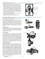
Page 7: ...ectly onto a wall or a 2 x 4 electrical box When the 070 is wall mounted the wiring should enter through the back or bottom of the enclosure Do not mount the 070 with the conduit knockout facing upwar...

Page 8: ...y to the pipe using the cable tie provided Insulation should be placed around the sensor to reduce the effect of air currents on the sensor measurement Immersion Well If a Universal Sensor is mounted...

Page 9: ...asure between 21 6 to 26 4 V ac If the voltage is below this range measure the line voltage side of the transformer The voltage should measure between 103 5 to 126 5 V ac Testing the Thermostats If th...

Page 10: ...by pressing the Item button once the boiler stage 2 turns on Using an electrical meter measure for continuity over the boiler stage 2 terminals Testing the Boiler Modulating Output This test applies f...

Page 11: ...ower H8005B Made in Canada Use at least 167 F 75 C conductors Stage 2 Stage 1 Description The House Control 400 operates an On Off boiler with indirect Domestic Hot Water The boiler is operated using...

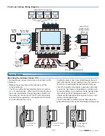
Page 12: ...2 18 AWG Expansion tN4 Boil C tN4 Modulating Boiler 1 R C L N 313 red black black Menu House Control 400 Item Com Boil Out DHW Vlv C Vlv C Vlv C Zone 3 Zone 1 Zone 2 Zone 4 Vlv C Com Zone 1 Zone 2 Zon...

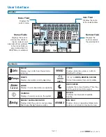
Page 13: ...er UNOCCUPIED Indicates that a User Switch or Timer has put the system into UnOccupied BOILER Indicates that the boiler should be heating MAX MIN MIN MAX Displays when an operating temperature reaches...

Page 14: ...ng Select the appropriate menu using the Menu button Select the item using the Item button Use the Up or Down button to make the adjustment Default Item When navigating menus the display reverts back...

Page 15: ...N SECTION E Current percent modulation of the boiler s burner The boiler modulation increases when the boiler supply is less than the boiler target The boiler modulation decreases when the boiler supp...

Page 16: ...the year Recommendations High mass radiant floor 120 F 50 C Low mass radiant floor 140 F 60 C Fancoil or air handling unit 190 F 90 C Copper fin tube convector 180 F 80 C Radiators 160 F 70 C Low prof...

Page 17: ...y available when a schedule or User Switch is present on the system Off 1 2 3 4 5 Default 2 Installer DHW MODE SECTION C Selects the DHW mode of operation The mode determines the zone and boiler syste...

Page 18: ...Default 180 F 82 0 C Installer SETPOINT SECTION D The minimum boiler target temperature when a Setpoint Call is present ADJUST F or C Default F Installer User UNITS Selects units for temperature displ...

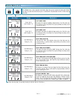
Page 19: ...NITOR hr Boil System Pumps 0 to 9999 Hours Default 0 hr RUN TIME BOIL SYSTEM PUMP The total running time of the Boil System Pump since this item was last cleared Press and hold the Up and Down buttons...

Page 20: ...access and shows the fewest possible items When set to USER all thermostats are locked and the number of thermostat settings available are reduced OFF SEL Default Off FACTORY DEFAULTS Loads the factor...

Page 21: ...ler target is determined by the control using the boiler heating curve boiler minimum boiler design and outdoor design settings together with indoor temperature feedback from the thermostats The heati...

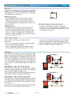
Page 22: ...DHW MODE 1 DHW in Parallel no Priority When a DHW Call is present the DHW pump is activated The boiler system pump does not turn on but may operate based on either a Boiler or Setpoint Call It is assu...

Page 23: ...nt of time for DHW priority during cold weather During warm weather the DHW priority is 120 minutes During cold weather the DHW priority is 15 minutes Once the allowed time for priority has elapsed th...

Page 24: ...re is a space heating target the boiler operates at that target for 15 minutes If after 15 minutes there is still a Setpoint Call the con trol will shut off all boiler heating zones and target the Set...

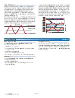
Page 25: ...st operate before the internal boiler control allows an external signal to operate the burner After the Modulation Delay has elapsed the control uses PID logic to change the boiler firing rate signal...

Page 26: ...boiler based on the heating load As the load increases the differential will decrease to minimize temperature swings As the load decreases the differential will increase to prevent short cycling This...

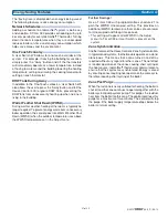
Page 27: ...ssary boiler operation the control goes into Warm Weather Shut Down WWSD when the outdoor temperature rises above the WWSD temperature set in the Adjust menu Energy Saving Features Section G Further S...

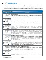
Page 28: ...for heat the control no longer controls the boiler Instead the control provides a boiler enable and the boiler operates on its aquastat limit until the sensor is repaired The control will not operate...

Page 29: ...t 4 expansion terminals The 400 is a Master Device and no other tekmarNet reset controls can be added to the tekmarNet 4 expansion terminals If one has been added remove it from the system DEVICE ERRO...

Page 30: ...the control is aware that the DHW tank requires heat DHW tank reading Ensure the DHW tank temperature is accurate and replace if necessary Burner symbol on LCD If the burner symbol is on the LCD there...

Page 31: ...Setting OUTDOOR DESIGN BOILER TYPE BOILER DESIGN BOILER MINIMUM BOILER MOTOR MINIMUM MODULATION MODULATION DELAY WWSD OCCUPIED Item Setting WWSD UNOCCUPIED DHW MODE DHW EXCHANGE DHW OCCUPIED DHW UNOCC...

Page 32: ...r misuse or has been damaged by modifications alterations or attachments made subsequent to purchase which have not been authorized by tekmar or if the Product was not installed in compliance with tek...

Reviews: