background image

9

98-05242-ENUS R4

Matrix

®

 Pro GS

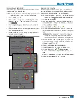
Minimum Duty Cycle Right Test

Minimum Duty Cycle Right sets the minimum amount of drive required 

to begin steering the vehicle to the right. 

NOTE:  If the valve frequency is set below 15 Hz (non proportional), set 

the amount of drive to “25.0”. Cycle test is not necessary.

1.  Press the KEYPAD icon  .
2.  While the vehicle is moving in a slow forward straight line motion 

between 1.0 mph and 8.0 mph / 1.5 - 13.0 km/h (0.4 - 3.6 m/s), 

press 

 Test Right 

.

3.  Press the engage/disengage switch or foot switch to activate the 

test.

4.  Slowly increase the duty cycle number using the UP arrow 

 until 

the vehicle begins to turn right.

5.  Turn the steering wheel or press the engage/disengage switch or 

foot switch to complete the test.

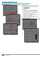
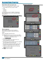
Figure GS-18: Minimum Duty Cycle Test

Maximum Duty Cycle Test

Maximum Duty Cycle sets the maximum speed that the wheels will 

steer from lock to lock. For recommendations and factory settings for 

the FieldPilot or UniPilot setup values, see chart on page 21.

NOTE:  If the valve frequency is below 15 Hz (non proportional), set the 

value to 100. Speed will be established during the Valve Test.

1.  Press the KEYPAD icon  .
2.  While the vehicle is moving in a slow forward motion between 1.0 

mph and 8.0 mph / 1.5 - 13.0 km/h (0.4 - 3.6 m/s), turn the wheels 

all the way to the left (or right).

3.  Press the RIGHT arrow   (or LEFT arrow  ).
4.  Press the engage/disengage switch or foot switch to activate the 

test. This will start a timer as well as turn the vehicle to the right (or 

left).

WARNING! 

When using a UniPilot, the UniPilot will move the 

steering wheel very quickly.  Keep loose clothing, hair and 

hands away from the steering wheel while preforming this test.

5.  When the wheels are all the way to the right (or left), stop the test 

by pressing the engage/disengage switch or foot switch. The time 

displayed is the lock to lock time. 

6.  Repeat to perform procedure to the opposite side.
7.  Compare the lock-to-lock time with the recommended time.
8.  Press the UP/DOWN arrows 


 to adjust the value.


►Lock-to-lock time is too low (turning too fast) – decrease the 

value 

►Lock to lock time is higher (turning too slow) – increase the value

9.  Repeat until recommended lock time is achieved.

Summary of Contents for MATRIX PRO570gs

Page 1: ...Assisted Auto Steering Setup Guide TeeJet Technologies 1801 Business Park Drive Springfield Illinois 62703 USA www teejet com For use with software version 3 0x 98 05242 ENUS R4 English US TeeJet Tech...

Page 2: ...TEEJET TECHNOLOGIES HAS BEEN ADVISED OF SUCH DAMAGES ARISING FROM TEEJET TECHNOLOGIES SOFTWARE Safety Information TeeJet Technologies is not responsible for damage or physical harm caused by failure t...

Page 3: ...e Frequency 7 Minimum Maximum Duty Cycle Tests 8 Minimum Duty Cycle Left Test 8 Minimum Duty Cycle Right Test 9 Maximum Duty Cycle Test 9 Steering Settings 10 Coarse Steering Adjustment 11 Fine Steeri...

Page 4: ...n the screen Figure GS 2 Information screens Dimming backlight brightness to reduce heat Previous backlight brightness will be restored when unit reaches a safe temperature Overheat Protection Drop Do...

Page 5: ...tion Working Width Applied Area Alarm Straight Mode Boom Offset Direction Antenna to Boom Distance Overlap Delay On Off Times Spreader Mode Setup Type TeeJet Antenna to Disks Distance Overlap Delay On...

Page 6: ...ort GPS Status displays information regarding GGA VTG Data Rates Number of Satellites HDOP PRN GGA Quality GPS Receiver Receiver Version and UTM Zone Program allows direct programming of the GPS recei...

Page 7: ...onfiguration options 1 Press UNIT SETUP bottom tab 2 Press CONFIGURATION side tab 3 Select from AutoSteer used to enable disable assisted auto steering as well as establish valve setup settings steeri...

Page 8: ...eering Adjustment Fine Steering Adjustment Deadband and Lookahead Valve Test used to verify if steering is directed correctly Valve Diagnostics used to test the valves to see if they are connected pro...

Page 9: ...maximum speed that the wheels will steer from lock to lock Figure GS 13 Valve Setup Valve Type Valve type is used to set the type of steering valve For recommendations and factory settings for the Fi...

Page 10: ...hile manually operating hydraulic steering circuits Keep others away and stay clear of mechanical linkage Figure GS 16 Duty Cycle Tests Minimum Duty Cycle Left Test Minimum Duty Cycle Left sets the mi...

Page 11: ...ge 21 NOTE If the valve frequency is below 15 Hz non proportional set the value to 100 Speed will be established during the Valve Test 1 Press the KEYPAD icon 2 While the vehicle is moving in a slow f...

Page 12: ...ect from Coarse Adjustment used to select how aggressively the vehicle maintains a guideline in Straight AB Guidance Fine Adjustment used to select how aggressively the vehicle maintains a guideline i...

Page 13: ...guideline or not approaching it fast enough DOWN arrow if the vehicle is oscillating rapidly or overshooting the guideline Figure GS 21 Coarse Steering Adjustment Fine Steering Adjustment Fine Steerin...

Page 14: ...too responsive DOWN arrow if the vehicle remains consistently off the guideline Figure GS 23 Deadband Lookahead Lookahead used during Straight AB Guidance mode to adjust the vehicle s approach to the...

Page 15: ...y Keep loose clothing hair and hands away from the steering wheel while preforming this test 5 Press the engage disengage switch or foot switch when the wheels are all the way to the right The time di...

Page 16: ...ft Left and right connections to valve are reversed Steering Valve With Master Solenoid 1 Select Valve Diagnostics 2 Activate the Master check box 3 Activate the Left or Right check boxes associated w...

Page 17: ...Magnetic Pressure Figure GS 27 Options Steering Wheel Sensor Magnetic Pressure Steering Angle Sensor Steering Angle Sensor is used establish the Steering Angle Sensor SAS as the primary feedback sens...

Page 18: ...S is installed NOTE A GPS signal is required for this test RECOMMENDATION Have a large area of clear space available to perform test cycles Vehicle speed must be between 1 0 mph and 8 0 mph 1 5 13 0 k...

Page 19: ...t cycle Typical operating speed must be maintained for at least 30 seconds 1 Establish and or activate a Straight AB guideline 2 Select On Line Calibration 3 Engage assisted auto steering guidance on...

Page 20: ...t correction 5 Press RETURN arrow or CONFIGURATION side tab to return to the main Configuration screen NOTE If FieldPilot or UniPilot is being used a Tilt Gyro Module is built into the system NOTE Ant...

Page 21: ...ointing in the primary direction of travel Choose a calibration site that is as level as possible To calibrate the SCM TGM 1 Position the vehicle on a level surface Let vehicle sit settle for at least...

Page 22: ...Steering Status Green engaged actively steering Yellow enabled all conditions have been met to allow for assisted auto steering Red disabled all conditions have not been met to allow for assisted auto...

Page 23: ...0 Maximum Duty Cycle 50 25 100 100 100 Lock to Lock Time 0 seconds 5 6 seconds Coarse Steering Adjustment 25 0 1 0 100 0 25 25 Fine Steering Adjustment 25 0 1 0 100 0 25 25 Deadband 1 1 10 1 1 Lookah...

Reviews: