20
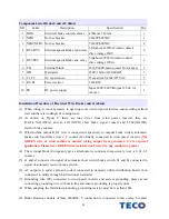
Component List of Brake Control Cabinet
NO Label
Description
Specification
Qty.
1 BOX
Electrical brake control cabinet
470mm x 320mm
1
2 NFB1
No fuse breaker
20A/2P/300VAC
1
3 NFB2,NFB3 No fuse breaker
50A/3P/600VAC
2
4 RY1~RY6
Electromagnetic Brake main relay
35A(above)/220VAC(main contact)
drive voltage 220V
6
5 RY7,RY8
Electromagnetic Brake aux. relay
5A(above)/220VAC(main contact)
drive voltage 12Vdc
2
6 TB
Terminal block
12x2P 600V/main contact 30A (above)
1
7 WH
Wattmeter
220V/10(30)A/(50/60HZ)
1
8 C1,C2
AC capacitance
X capacitor/0.22uF/275VAC
2
9 R1~R3
Power resistor 3
Ω
/1KW 3
10 PS
DC power supply
Input 200V~260V/Output 12Vdc; 1A
(above)
1
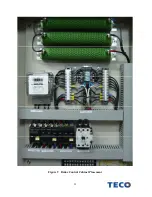
Installation Procedure of Electrical Wire Brake control cabinet
(1)
When wiring, it is not necessary to open top cover of wind power inverter, ensure wiring is fixed
well and there is no danger of coming loose.
(2)
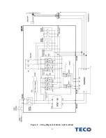
As shown on Figure 8, there are nine wires from wind power inverter, they are
R,S,T,L,N(12AWG), and al, a2(12AWG) short brake signal contact and b1,b2(12AWG)
resistor brake contact.
(3)
Wind turbine output R,S,T wire is connected respectively to manual brake switch, automatic
brake switch and three relays’ C contact then finally connected to wind power inverter.
(The
GREEN wire of wind turbine is neutral wiring output from generator, it’s for special
application. Please leave GREEN wire isolated, don’t wire it to any conductive goods.)
(4)
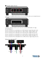
The terminal block (European type) as attachment is connected respectively to a1, a2, b1, b2
contact.
(5)
a1 and a2 connected to signal of automatic short circuit brake switch, b1 and b2 connected to
signal of automatic resistor brake switch.
(6)
AC output is a spiral exclusive socket connected to domestic utility distribution board, then
connected to utility through bi-directional wattmeter.
(7)
Grounding wire (PE) connected to wind power inverter and system grounding, please avoid
connecting grounding wire with main line and ensure grounding is properly done.
(8)
When adopting the third kind grounding, grounding resistor must be less than 10
Ω
.
(9)
Brake Resistor consists of three 3
Ω
/1KW; Y connection is connected to three relay b contact

